
Cube shaped lamp and projection device for single slide or digital projection

a projection device and cube shaped technology, applied in the direction of slide projectors, instruments, optics, etc., can solve the problems of not having all the features described not having a single slide projector, and not having a cubic assembly disclosed in such examined prior art, etc., to achieve low cost of the device, bright illumination, and low cost

Inactive Publication Date: 2007-06-28
DANIEL SIMON +1
View PDF15 Cites 14 Cited by
  • Summary
  • Abstract
  • Description
  • Claims
  • Application Information

AI Technical Summary

Benefits of technology

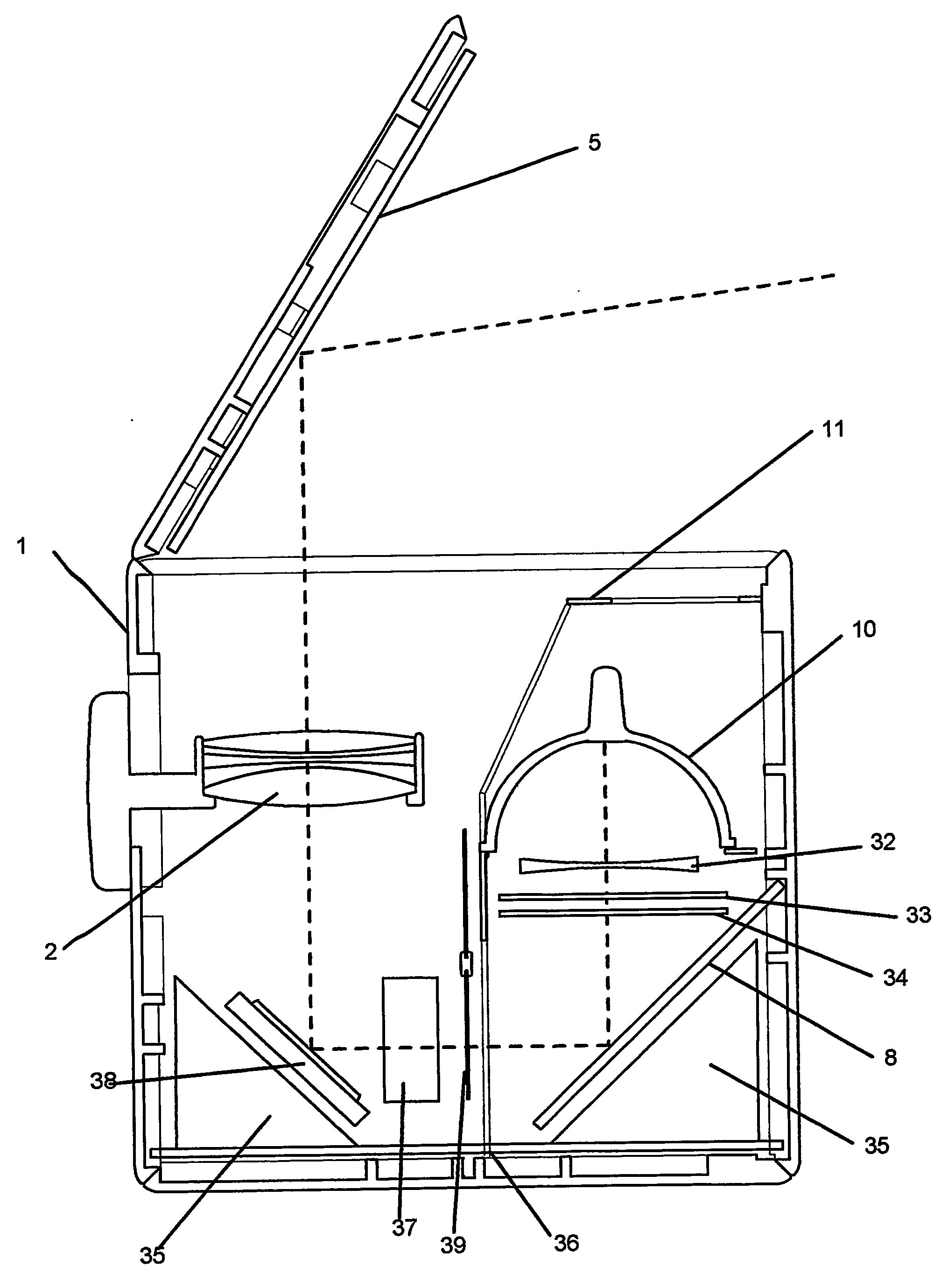
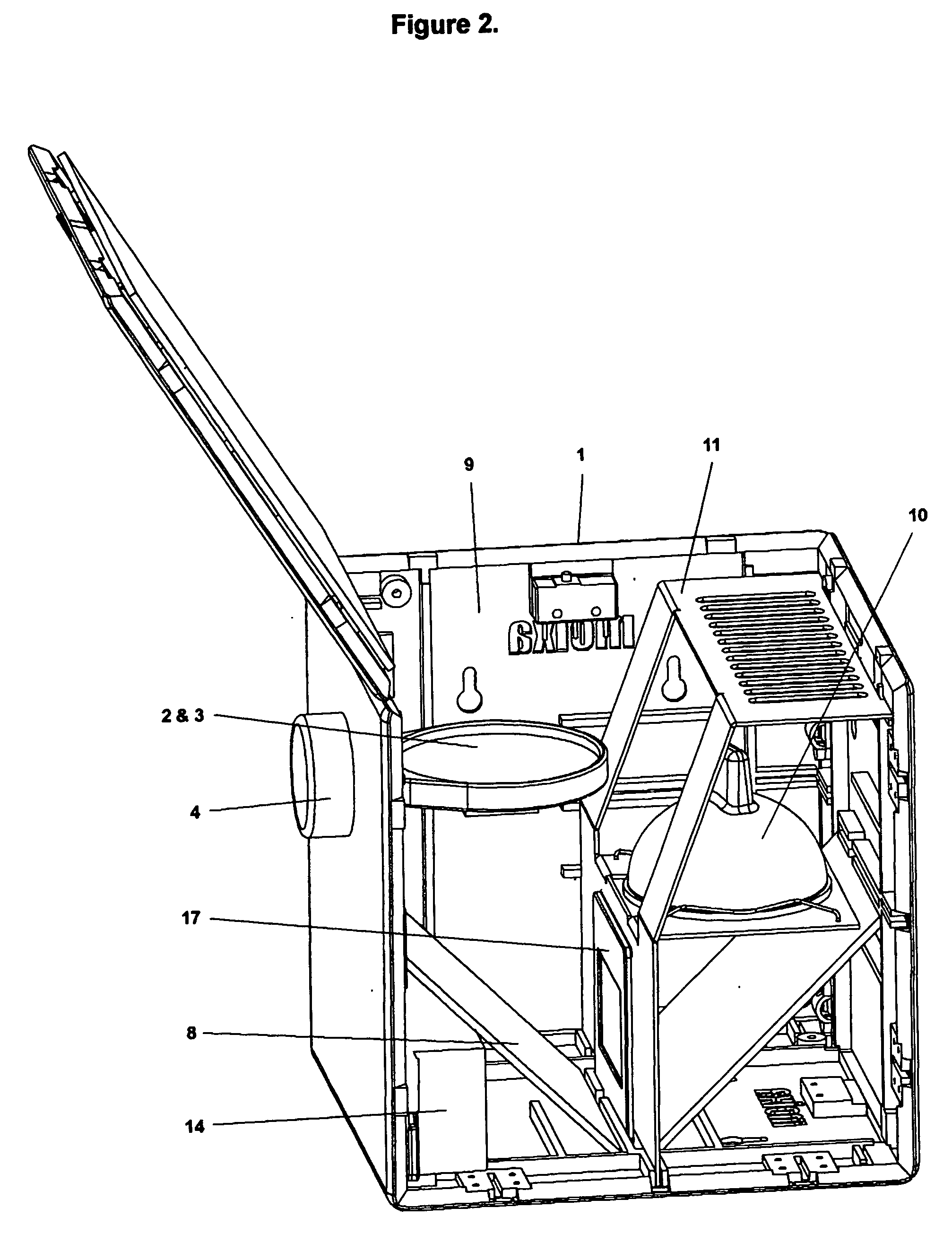
[0009] The lamp and projection device of the present invention, in its preferred embodiment, comprises a cube shaped assembly constructed from six identical modular faces that interlock at the edges by means of adjacent recesses and protrusions on opposed edges. Said cube shaped assembly forms a box containing an illumination and projection system consisting of a lamp or at least one light-emitting unit, a electrical transformer unit and switches, a plurality of reflecting mirrors and at least one condensing lens arranged in a suitable optical arrangement around a mid vertical axis of the cube where a slide or digital means can be positioned. The top face of the cube functions as a lid which is arranged to be hinged at one edge and to support a mirror on the inside surface and is capable of being positioned at any angle between a closed position and an open perpendicular position such that it can project an image of a slide onto a nearby wall or projection surface, or onto a ceiling when fully open. Said lid would compress a micro-switch when closed to turn the lamp off or on when opened. Said faces are designed to have an identical interior structure consisting of grooves and support structures that hold and fix the components of the illumination and projection system such as the reflecting mirrors, lens holder, bulb holder and electrical components. These faces are designed such that grooves perform different functions (e.g. hold a slide or lens holder) or are not used depending on their position and rotation in the cube assembly. The interior of the cube also houses a sheet metal bulb holder which is bent and punched to hold a lamp and dissipate heat and to slot into appropriate grooves in the cube side casing as well as to reduce vertical light leakage. Said lens is arranged to be supported in a holder which slots into grooves in the cube side casing and passes through a punched recess in the casing to connect to a control button in such a manner as to enable vertical sliding and control of lens position for focusing. The overall geometry of the cube and symmetrical arrangement of bulb, lens and mirrors about the central cube axis containing the slide provides a simple but effective optical arrangement for projection of a single slide. Said bulb is positioned close to the central axis and in a preferred embodiment consists of a low voltage parabolic bulb of specific spread matching the geometry of the cube so as to provide equal illumination across the slide surface.

Problems solved by technology

However, no such prior art has all the features described and claimed herein.
As an example no such examined prior art discloses the cubic assembly using modular panels which make use of a hinged mirrored cube lid to project the image onto a desired projection surface.
Nor does prior art provide for a single slide projector which uses the side casing in such an ornamental design as described herein to function as a soft illumination lamp.

Method used


Image

  • Cube shaped lamp and projection device for single slide or digital projection
  • Cube shaped lamp and projection device for single slide or digital projection
  • Cube shaped lamp and projection device for single slide or digital projection

Examples


Embodiment Construction

[0026] The preferred embodiments of the invention will now be described with reference to the accompanying drawings herein:

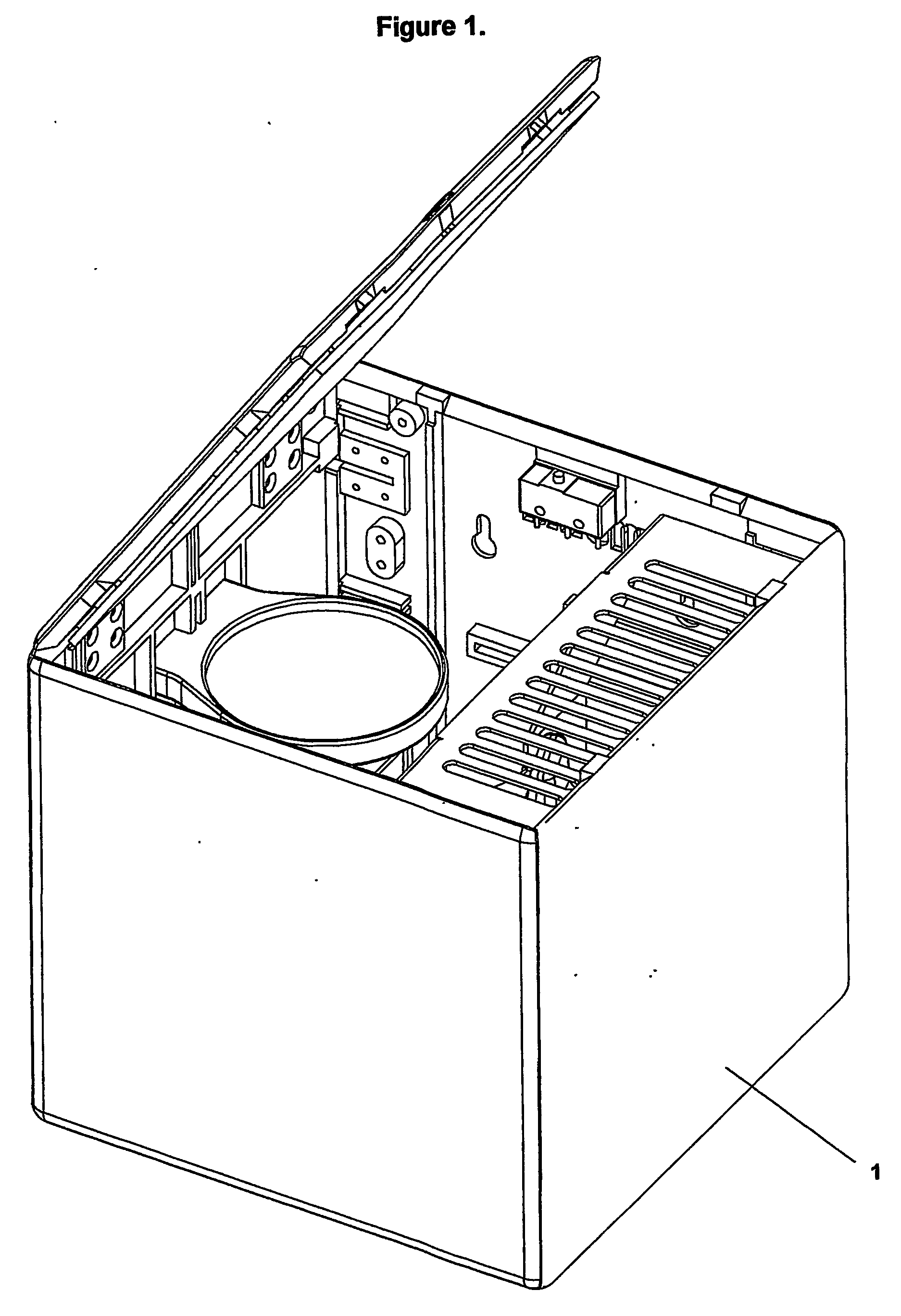
[0027] Referring to FIG. 1, which shows the overall lamp and projection device 1 when fully assembled showing the lid 7 open at an angle to project an image onto a nearby wall surface as it might appear when in use.

[0028] Referring now to FIG. 2, which shows the overall lamp and projection device 1 with one cube side 9 removed for clarity. The device comprises six identical side face panels 9 arranged at different rotations to form a cube. These interlock by means of protrusions 26 and recesses 20 on opposed faces. The left side casing 9 supports a lens assembly comprised of a lens 2 in a lens holder 3 bound between vertical struts 24 and is connected to a lens button 4 via a punched slot in the central groove 23 such that the overall lens assembly can be moved vertically. The device shows the metal bulb plate 11 supporting a bulb 10 and fixing into the cube s...


PUM


Abstract

A lamp and projection device for a single slide or digital imaging means comprising six substantially identical faces assembled to form a cube body which supports an illumination system consisting of a light-emitting unit, a electrical transformer unit and switches, a plurality of reflecting mirrors and at least one condensing lens, and a slide or digital light engine. Said overall cube body having a hinged face at the top supporting a reflecting mirror on the inside surface which can be positioned at any angle to allow projecting an image onto a ceiling or onto an adjacent surface, with a micro-switch acting to switch on the device when opened. Said lens being adjustable by means of an external button to enable focusing. The overall faces being formed from a semi-translucent material to enable soft illumination. Said overall device being implemented as a single slide projector / decorative lamp, digital photo projector or video projector.

Description

BACKGROUND OF THE INVENTION [0001] 1) Field of the Invention [0002] This invention relates to a cube shaped lamp and projection device which when opened can project a single slide or digital image onto a ceiling, wall or projection surface. The present invention in a preferred embodiment comprises six substantially flat and identically moulded side casings that are modular and can be assembled to form a cube with the top surface hinged so as to provide a lid and reflection surface capable of being projecting at various angles and also soft illumination through semi-translucent cube panels. In a further embodiment the projection apparatus uses a translucent LCD in place of the slide or a digital light engine where a corner mirror is a digital micro-mirror device (DMD) with associated filters, light tunnel and colour wheels to provide a projection device capable of projecting either static digital photographs from inserted electronic data media or a video or computing display. [0003] ...

Claims


Application Information

Patent Timeline
IPC IPC(8): G03B21/28G03B21/14
CPCG03B21/14G03B21/001G03B21/145
Inventor DANIEL, SIMONWRIGHT, CHRISTOPHER
Owner DANIEL SIMON
Learn More