Light emitting device
a technology of light-emitting devices and components, which is applied in the direction of optical radiation measurement, identification means, instruments, etc., can solve the problems of increasing the cost of the more kinds of components, and the inferior efficiency of the assembly job of the apparatus, so as to reduce the kinds of components
- Summary
- Abstract
- Description
- Claims
- Application Information
AI Technical Summary
Benefits of technology
Problems solved by technology
Method used
Image
Examples
first embodiment
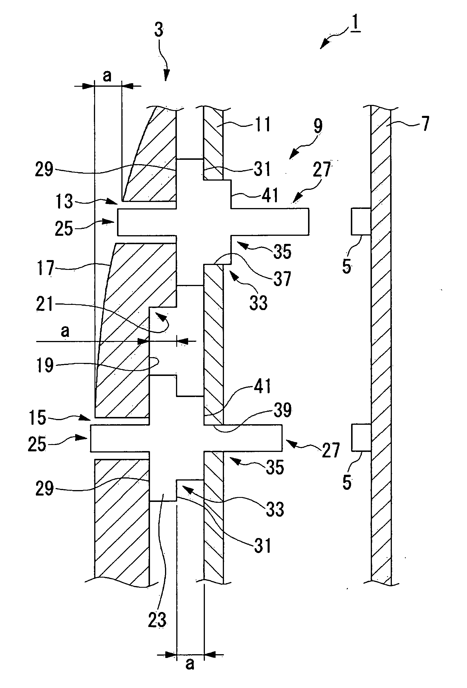
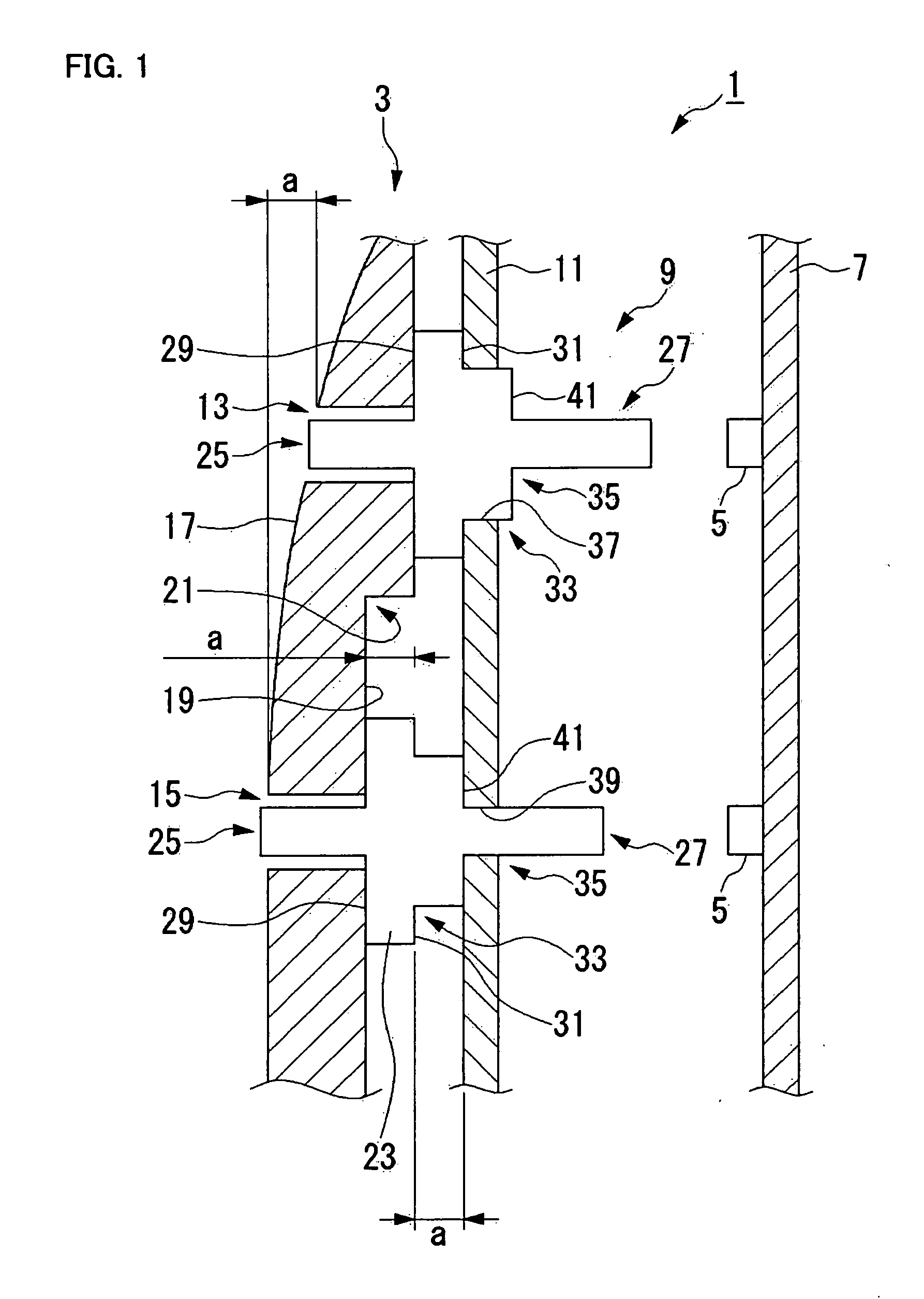
[0050]FIG. 1 shows an LED apparatus in the invention. Referring to FIG. 1, the LED apparatus 1 has a housing 3, a substrate 7 on which LED elements 5 being light emitting elements are mounted, LED light guide plates 9 which guide light beams emitted by the LED elements 5, and a keeper plate 11 which holds the LED light guide plates 9. The LED light guide plates 9 are held in a state where they are interposed between the housing 3 and the keeper plate 11. The LED light guide plates 9 and the keeper plate 11 correspond to light-emitting-element light guide components and a holding member in the invention, respectively.
[0051] The housing 3 is made of a resin, and it is provided with two LED windows 13, 15 as shown in the figure. The front surface 17 of the housing 3 is formed of a curved surface, so that the heights of the front surface 17 of the housing 3 in the LED windows 13, 15 are different.
[0052] By the way, in the ensuing description, the “heights of the front surface 17 of the...
second embodiment
[0070]FIGS. 2-5 show an LED apparatus in the invention. Hereafter, items described in conjunction with FIG. 1 shall be omitted on occasion.
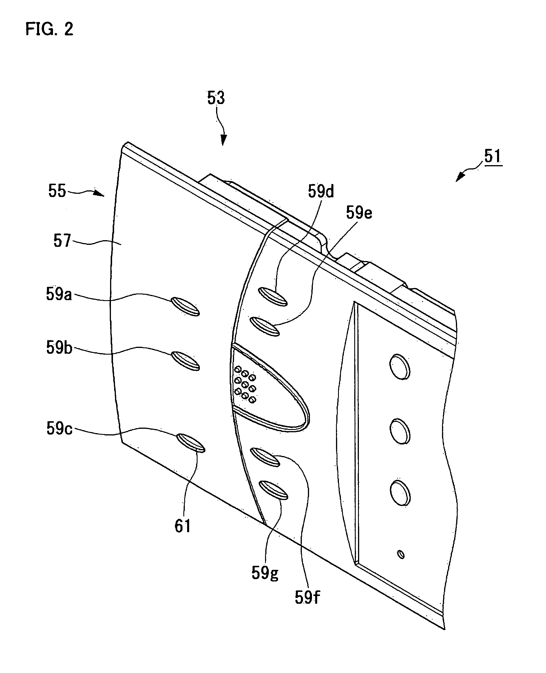
[0071]FIG. 2 is a perspective view of the external appearance, in which an electronic equipment 51 includes an LED apparatus 53, and an operating panel 55 forms part of the housing of the electronic equipment 51. Seven LED windows 59a-59g are provided in the front surface 57 of the operating panel 55, and each of these LED windows 59a-59g is substantially elliptic and penetrates through the operating panel 55. Since the front surface 57 of the operating panel 55 is formed of a curved surface, the height of the front surface 57 differs depending upon the positions of the LED windows 59a-59g. The end parts of LED light guide plates 61 are seen from the LED windows 59a-59g.
[0072]FIGS. 3A, 3B and 3C show the LED light guide plate 61. FIG. 3A is a perspective view, FIG. 3B is a front view, and FIG. 3C is a side view. The LED light guide plate 61 has ...
third embodiment
[0086] Next, FIG. 6 shows the invention. In FIG. 6, identical reference numerals are assigned to the same constituents as in FIG. 1, and these constituents shall be omitted from description.
[0087] Also in this embodiment, each of the substrate-side protrusions 27 of light guide plates 9 has a sectional shape which becomes smaller toward a substrate 7. However, whereas the substrate-side protrusion 27 in FIG. 1 becomes finer in stages, the substrate-side protrusion 27 in this embodiment has a taper portion 91, which becomes finer continuously. The taper portion 91 has a first taper portion 911 and a second taper portion 913. Both the first taper portion 911 and the second taper portion 913 are parts of the taper portion 911, and the second taper portion 913 is the part nearer to the distal end side of the taper portion 91 than the first taper portion 911. Besides, sectional shapes become smaller in the order of a base portion 90, the first taper portion 911 and the second taper porti...
PUM
 Abstract
Description
Claims
Application Information
 - R&D
- Intellectual Property
- Life Sciences
- Materials
- Tech Scout
- Unparalleled Data Quality
- Higher Quality Content
- 60% Fewer Hallucinations
Browse by: Latest US Patents, China's latest patents, Technical Efficacy Thesaurus, Application Domain, Technology Topic, Popular Technical Reports.
© 2025 PatSnap. All rights reserved.Legal|Privacy policy|Modern Slavery Act Transparency Statement|Sitemap|About US| Contact US: help@patsnap.com


