Optical pickup device and method of laying out the same

Inactive Publication Date: 2007-06-28
SANYO ELECTRIC CO LTD
View PDF2 Cites 6 Cited by
  • Summary
  • Abstract
  • Description
  • Claims
  • Application Information

AI Technical Summary

Benefits of technology

[0015] An object of the present invention is to provide an optical pickup device capable of minimizing a misalignment between a directio

Problems solved by technology

This can cause such a problem that the track direction rotates with respect to a parting line of a sensor pattern, hindering generation of a proper push-pull signal.
However, in this case, there is often a case in which the oscillation angle α may not be set to ±45° because of a laying out condition of optical components.
Consequently, a problem arises that a 4-split sensor may not be positioned at a position at which both a focus error signal and a tracking error signal (push-pull signal) become appropriate.
Moreover, a

Method used


Image

  • Optical pickup device and method of laying out the same
  • Optical pickup device and method of laying out the same
  • Optical pickup device and method of laying out the same

Examples


example 1

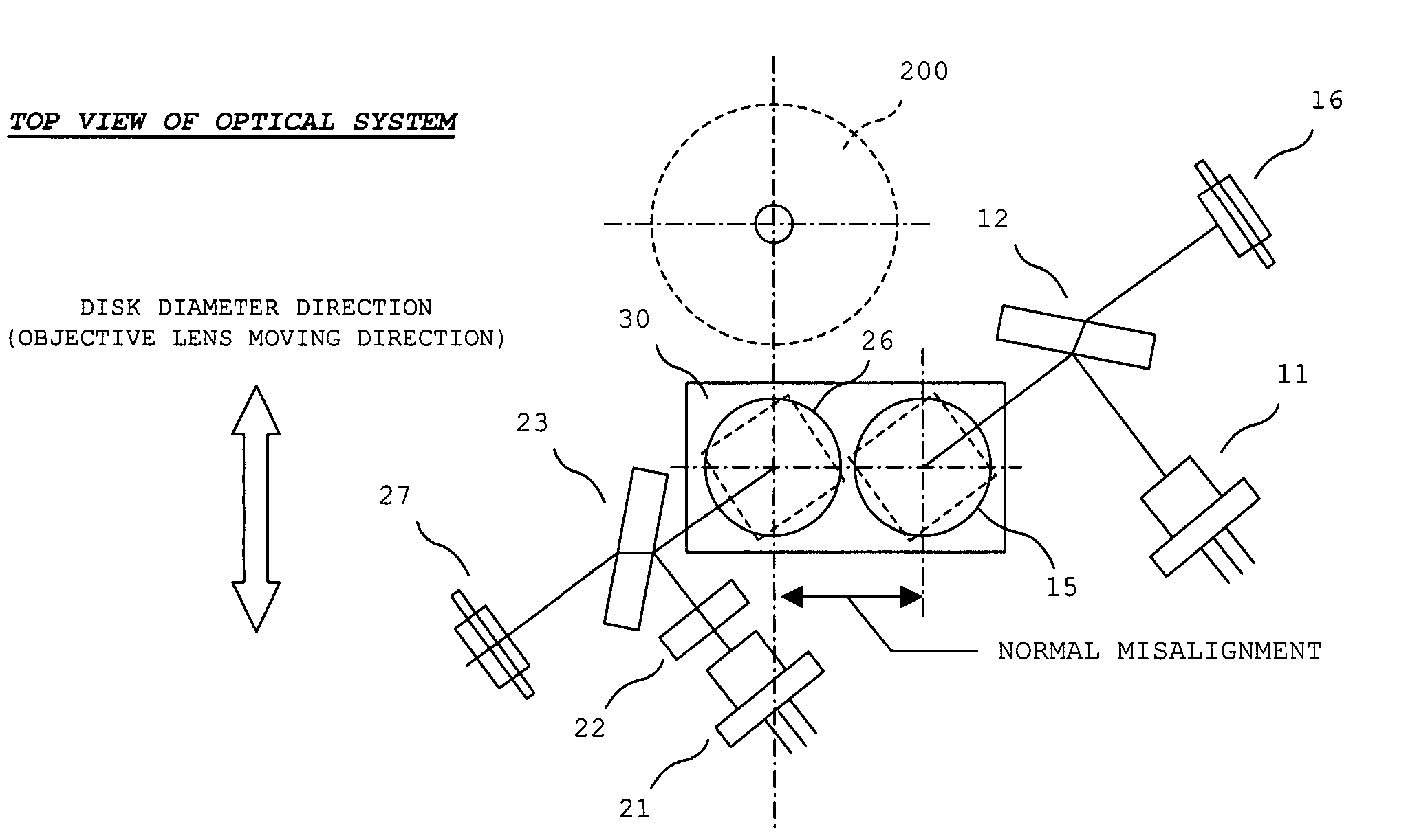
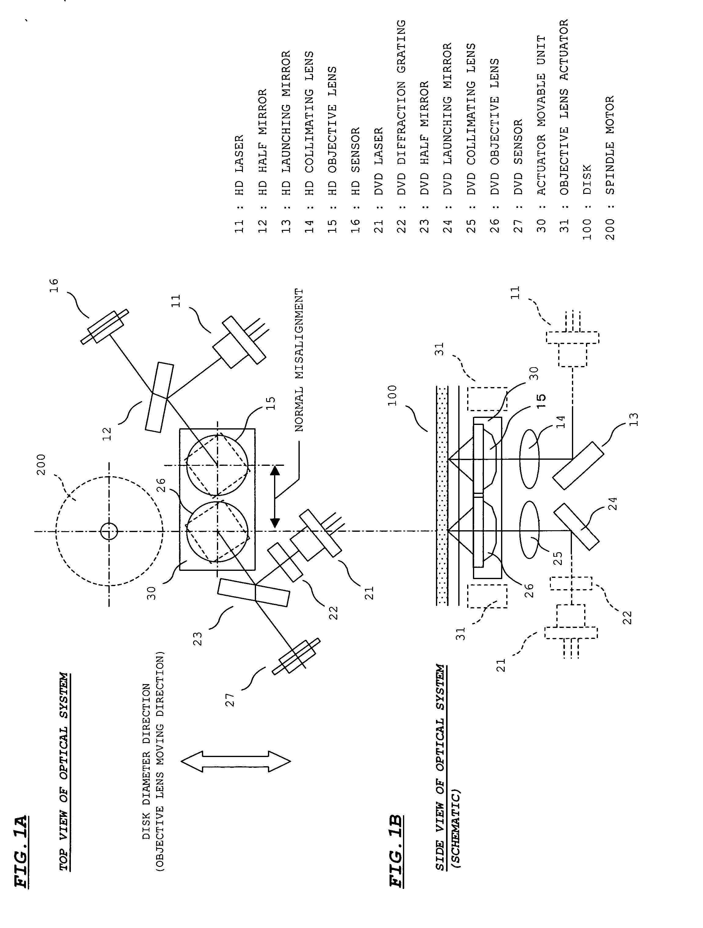
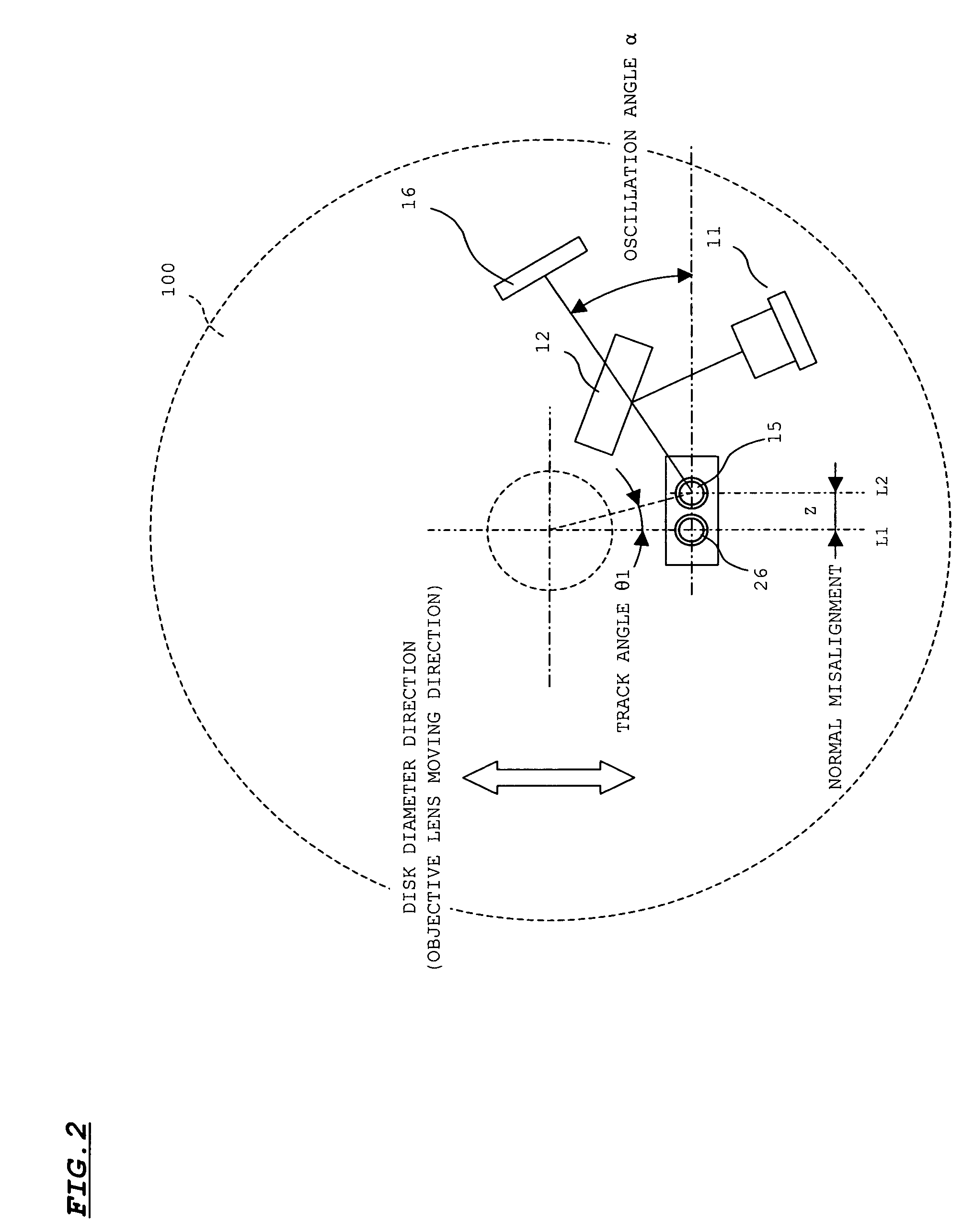
[0070] This example relates to the optical system shown in the above FIGS. 1A and 1B, in which a proper value for the oscillation angle α when the amount of the normal misalignment z for the HD objective lens 15 is fixed to Z=5 mm is obtained, and the position of the HD optical system is positioned according to the obtained oscillation angle. In this example, the HD objective lens 15 is positioned on the right side of the DVD objective lens 26 like in the case of the optical system shown in FIGS. 1A and 1B.

[0071] When the amount of the normal misalignment z for the HD objective lens 15 is 5 mm, referring to FIG. 16B, the maximum value θ1max and the minimum value θ1min for the track angle θ1 are respectively maximum value θ1max=13° and minimum value θ1min=5°. The oscillation angle α obtained by substituting these values to the above equation (4) is α=+54° and α=−36°.

[0072] Therefore, according to this example, the HD laser 11, the half mirror 12, and the HD sensor 16 are positioned...

example 2

[0089] This example relates to the optical system shown in the above FIGS. 1A and 1B, in which a proper value for the amount of the normal misalignment z for the HD objective lens 15 when the oscillation angle α is filed to −35° is obtained, and the position of the HD optical system is positioned according to the obtained amount of normal misalignment z. Note that in this example, the HD objective lens 15 is positioned on the left side of the DVD objective lens 26 unlike the optical system shown FIGS. 1A and 1B.

[0090] When the oscillation angle α of the HD objective lens 15 is +35°, from the equation (4), the maximum value θ1max and the minimum value θ1min of the track angle θ1 are required to satisfy the following relation.

(θ1max+θ1min) / 2=−10°,+80°  (5)

Here, (θ1max+θ1min) / 2=+80° is impossible. Consequently, the relation between the maximum value θ1max and the minimum value θ1min is defined as follows.

(θ1max+θ1min) / 2=−10°  (6)

Referring to FIG. 13, θ=Sin−1(Z / r) (r is a distanc...

example 3

[0096] In the Examples 1 and 2, the oscillation angle α and the amount of the normal misalignment z are adjusted so that the intermediate angle φave between φmin and φmax matches with ψ=45°, thereby making both the focus error signal and the tracking error signal ideal without deterioration. In other words, in these Examples, it is intended to improve the focus error signal and the tracking error signal by adjusting the positioning of the HD optical system so that the oscillation angle α and the amount of the normal misalignment z satisfies the equation (4).

[0097] In contrast, this example intends to improve the focus error signal and the tracking error signal by adjusting the direction of the PP parting line shown in FIGS. 6A and 6B. Specifically, it is intended to improve the focus error signal and the tracking error signal by adjusting the direction of the parting line of the 4-split sensor in a case in which ψ=45° shown in FIG. 3A and φave from the equation (3) do not match eac...


PUM


Abstract

An optical pickup device is provided, in which, supposing that an angle formed by the meeting of a straight line connecting a center of an optical disk and an accessing position of an HD objective lens with a diameter L of the optical disk is a track angle θ1, an oscillation angle α of an optical system including an HD laser, an HD half mirror, and an HD sensor, and a distance z of the HD objective lens are set so as to satisfy α−(θ1max+θ1min)/2=±45°, where θ1max is the track angle θ1 when the HD objective lens is positioned at an innermost circumference of the optical disk, and θ1min is the track angle θ1 when the HD objective lens is positioned at an outermost circumference of the optical disk.

Description

[0001] This application claims priority under 35 U.S.C. Section 119 of Japanese Patent Application No. 2005-376247 filed Dec. 27, 2005 and Japanese Patent Application No. 2005-377003 filed Dec. 28, 2005. BACKGROUND OF THE INVENTION [0002] 1. Field of the Invention [0003] The present invention relates to an optical pickup device and a method of laying out an optical system thereof, which is in particular suitable for use in a compatible optical pickup device capable of outputting laser light of a plurality of wavelengths as well as a method of laying out such a device. [0004] 2. Description of Related Art [0005] With the growing size of optical disks in their capacity, development of HD-DVDs (High Definition Digital Versatile Discs) using blue wavelength laser light has been pursued. Presently, optical pickup devices compatible for both of such HD-DVDs and existing DVDs have been under development. [0006] A typical configuration for such compatible optical pickup devices of this kind...

Claims


Application Information

Patent Timeline
IPC IPC(8): G11B7/00
CPCG11B7/0935G11B7/13G11B7/1374G11B2007/0006
Inventor NAGATOMI, KENJIKAJIYAMA, SEIJI
Owner SANYO ELECTRIC CO LTD
Why Eureka
Try Eureka