
Synchronous optical network (SONET) demarcation device

a technology of optical network and demarcation device, which is applied in the field of network communication, can solve the problems of removing the capability to remotely monitor and test the optical facility at the customer premises, and high cost of placing sonet multiplexer equipment at the customer premises, and achieve the effect of streamlining the disclosur

Inactive Publication Date: 2007-06-28
SBC KNOWLEDGE VENTURES LP
View PDF4 Cites 6 Cited by
  • Summary
  • Abstract
  • Description
  • Claims
  • Application Information

AI Technical Summary

Benefits of technology

[0036] One or more embodiments of the disclosure may be referred to herein, individually and / or collectively, by the term “invention” merely for convenience and without intending to voluntarily limit the scope of this application to any particular invention or inventive concept. Moreover, although specific embodiments have been illustrated and described herein, it should be appreciated that any subsequent arrangement designed to achieve the same or similar purpose may be substituted for the specific embodiments shown. This disclosure is intended to cover any and all subsequent adaptations or variations of various embodiments. Combinations of the above embodiments, and other embodiments not specifically described herein, will be apparent to those of skill in the art upon reviewing the description.
[0037] The Abstract of the Disclosure is provided to comply with 37 C.F.R. §1.72(b) and is submitted with the understanding that it will not be used to interpret or limit the scope or meaning of the claims. In addition, in the foregoing Detailed Description, various features may be grouped together or described in a single embodiment for the purpose of streamlining the disclosure. This disclosure is not to be interpreted as reflecting an intention that the claimed embodiments require more features than are expressly recited in each claim. Rather, as the following claims reflect, inventive subject matter may be directed to less than all of the features of any of the disclosed embodiments. Thus, the following claims are incorporated into the Detailed Description, with each claim standing on its own as defining separately claimed subject matter.

Problems solved by technology

Placing SONET multiplexer equipment at the customer premises is expensive.
This design, however, eliminates the capability to remotely monitor and test the optical facility at the customer premises.

Method used


Image

  • Synchronous optical network (SONET) demarcation device
  • Synchronous optical network (SONET) demarcation device
  • Synchronous optical network (SONET) demarcation device

Examples


Embodiment Construction

[0008] In view of the foregoing, the present invention, through one or more of its various aspects, embodiments and / or specific features or sub-components, is thus intended to bring out one or more of the advantages as specifically noted below.

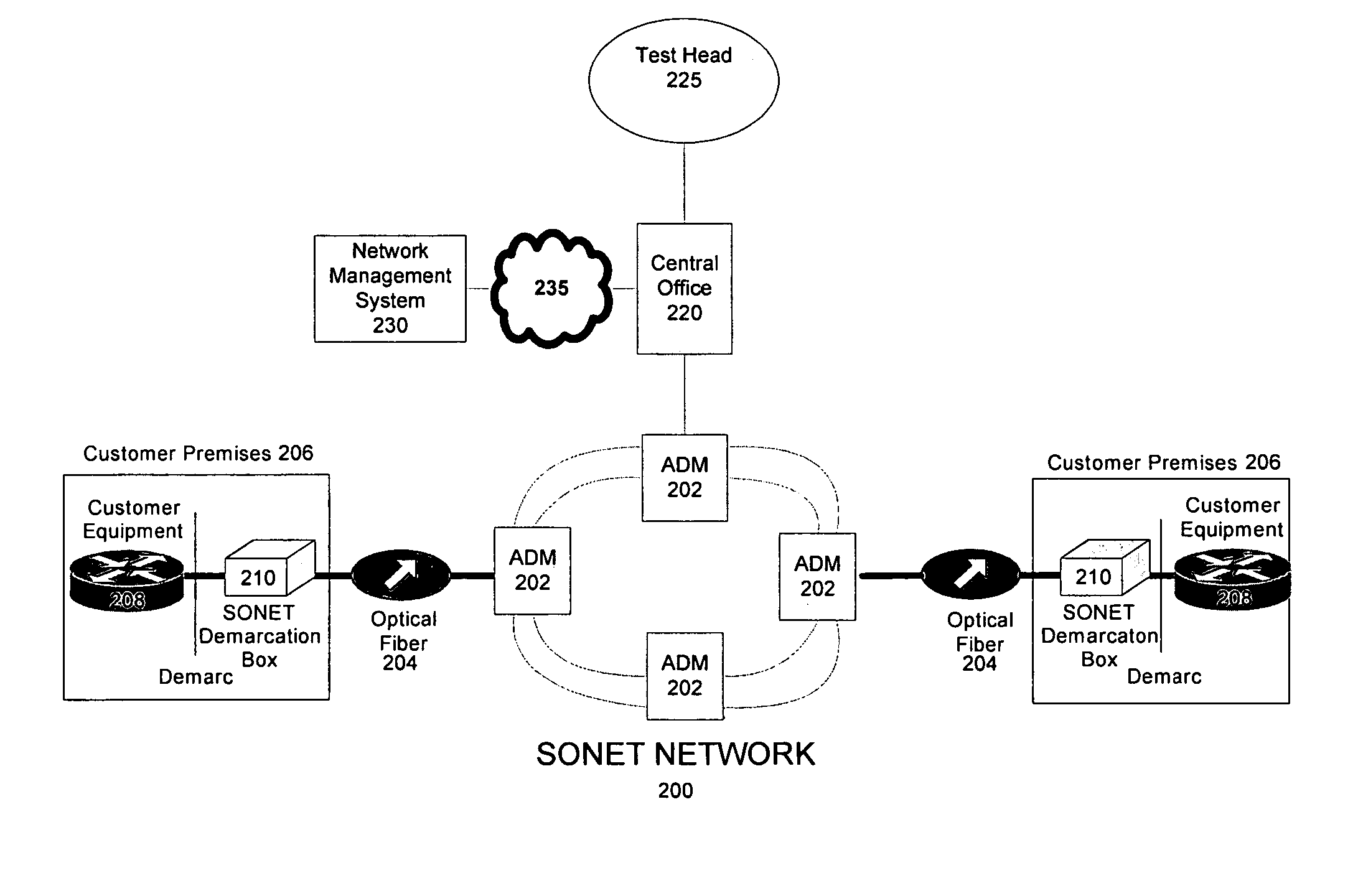
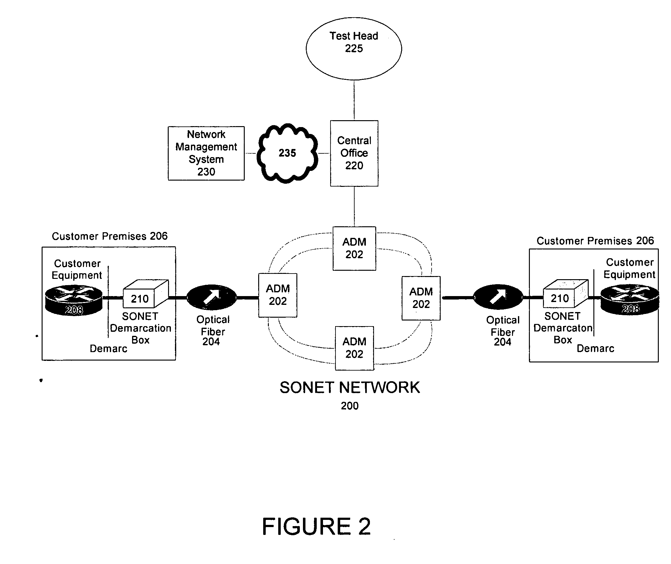
[0009] In one aspect of the present invention, a synchronous optical network (SONET) demarcation device for placement at a customer premises includes a SONET signal analyzer that extracts SONET data. The device also includes a SONET fault condition, performance statistics, and alarm generator to generate fault conditions, performance statistics, and alarms based upon extracted SONET data. The device further includes a transmitter to transmit the alarm and / or performance data to a remote site. The SONET demarcation device does not include ring functionality in one embodiment. In another embodiment, the SONET demarcation device does not include multiplexing functionality. The SONET demarcation device allows remote fault and performance monitori...


PUM


Abstract

A synchronous optical network (SONET) demarcation device can be placed on a customer premises to enable remote testing and trouble shooting of customer premises equipment. The device includes a SONET signal analyzer that extracts SONET data, such as section, line and path overhead. The SONET demarcation device also includes a SONET fault condition, performance statistics, and alarm generator that generates fault conditions, performance statistics, and alarms based upon the extracted SONET data. The device also includes a transmitter that transmits the alarm and / or performance data to a remote site. The SONET demarcation device does not include ring functionality and / or multiplexing functionality, thus being lower in cost than a SONET multiplexer.

Description

BACKGROUND [0001] 1. Field of the Disclosure [0002] The present disclosure relates to networking. More particularly, the present disclosure relates to a SONET demarcation box. [0003] 2. Background Information [0004] Currently, SONET services are designed with a SONET multiplexer on the customer premises. The multiplexers on the customer premises demultiplex to a lower rate signal and also enable remote fault and performance monitoring, testing and troubleshooting of the customer's optical circuit on an end-to-end basis. The SONET multiplexers typically have ring functionality. [0005] Placing SONET multiplexer equipment at the customer premises is expensive. Thus, edgeless equipment configurations have been proposed to eliminate the SONET multiplexer from the customer premises. This design, however, eliminates the capability to remotely monitor and test the optical facility at the customer premises. When customer trouble is reported, a technician must be dispatched (i.e., a truck rol...

Claims


Application Information

Patent Timeline
Patent Type & Authority Applications(United States)
IPC IPC(8): H04J1/16
CPCH04J3/14
Inventor SMITH, BARBARA E.
Owner SBC KNOWLEDGE VENTURES LP
Learn More