Turbo compressor

a compressor and turbine technology, applied in the direction of machines/engines, liquid fuel engines, light and heating apparatus, etc., can solve the problems of large mechanical loss, short service life of bearings, and large mechanical loss, so as to increase the critical speed without, prolong the service life of bearings, and reduce mechanical losses

Active Publication Date: 2007-06-28
DAIKIN IND LTD
View PDF16 Cites 26 Cited by
  • Summary
  • Abstract
  • Description
  • Claims
  • Application Information

AI Technical Summary

Benefits of technology

[0020]The present invention is made by taking the circumstances mentioned above into consideration, and an object of the present invention is to provide a turbo compressor which can elongate a service life of bearings by reducing a mechanical loss in the bearing part, and can increase a critical speed without shortening the axial length of impellers.

Problems solved by technology

Therefore, as to the bearing which supports a larger thrust load applied to the rotating shaft of the compressor, a mechanical loss becomes larger as the support load becomes larger, and there is a problem that a service life of the bearing becomes short.
Further, if the number of the bearings arranged is increased in order to elongate the service life of the bearings, there is a problem that the mechanical loss becomes large.
Accordingly, the number of the bearings to be used is increased, and there is a problem that the mechanical loss is large.
However, it is not preferable in the light of the compression efficiency to shorten the axial length of the impeller.
Further, in the turbo compressor in the patent document 2, the distance between the shaft support portions is elongated because of being supported near opposite end portions of the rotating shaft, causing a problem that the critical speed is lowered.

Method used


Image

  • Turbo compressor
  • Turbo compressor
  • Turbo compressor

Examples


first embodiment

[0047]The description will be given below of an embodiment in accordance with the present invention.

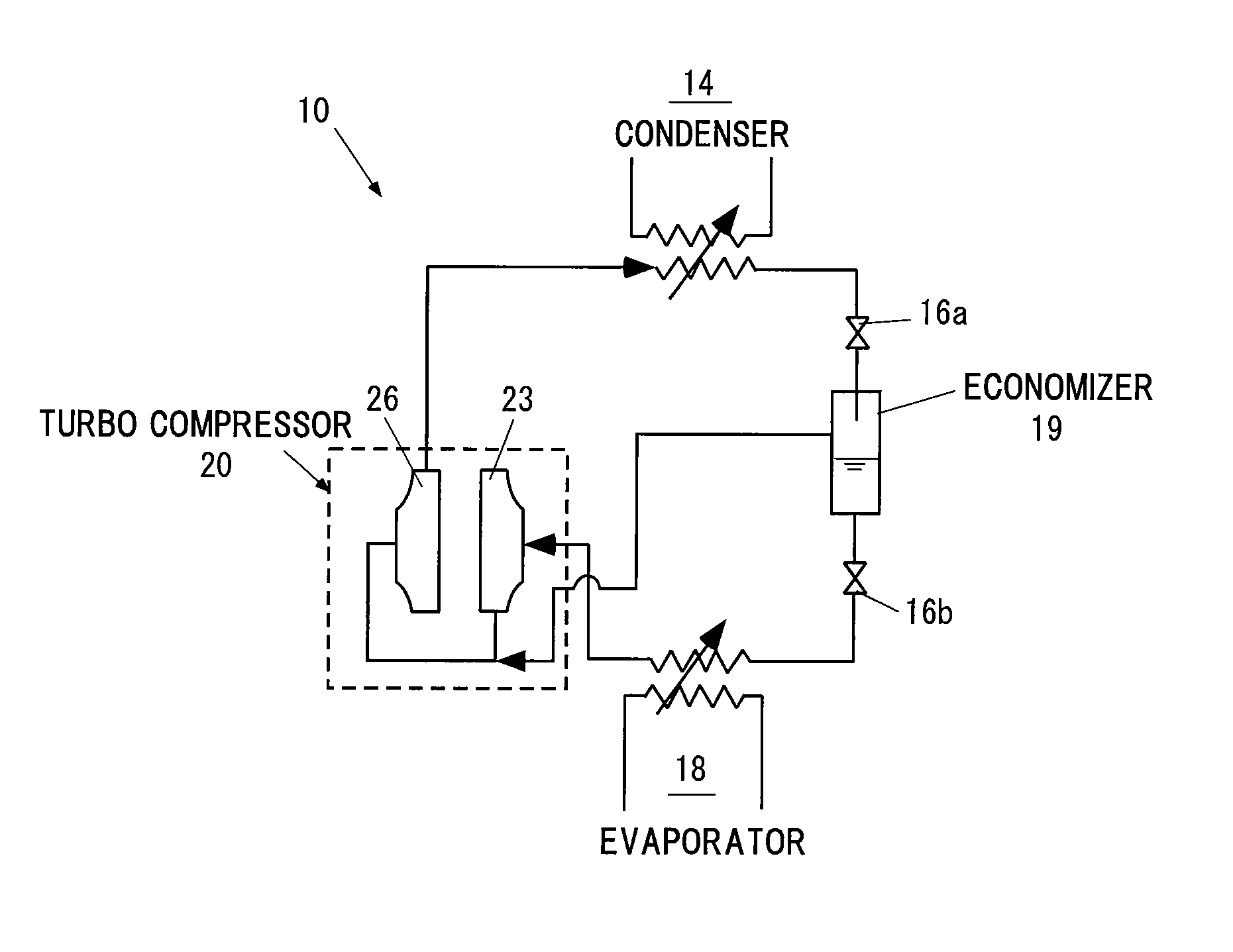
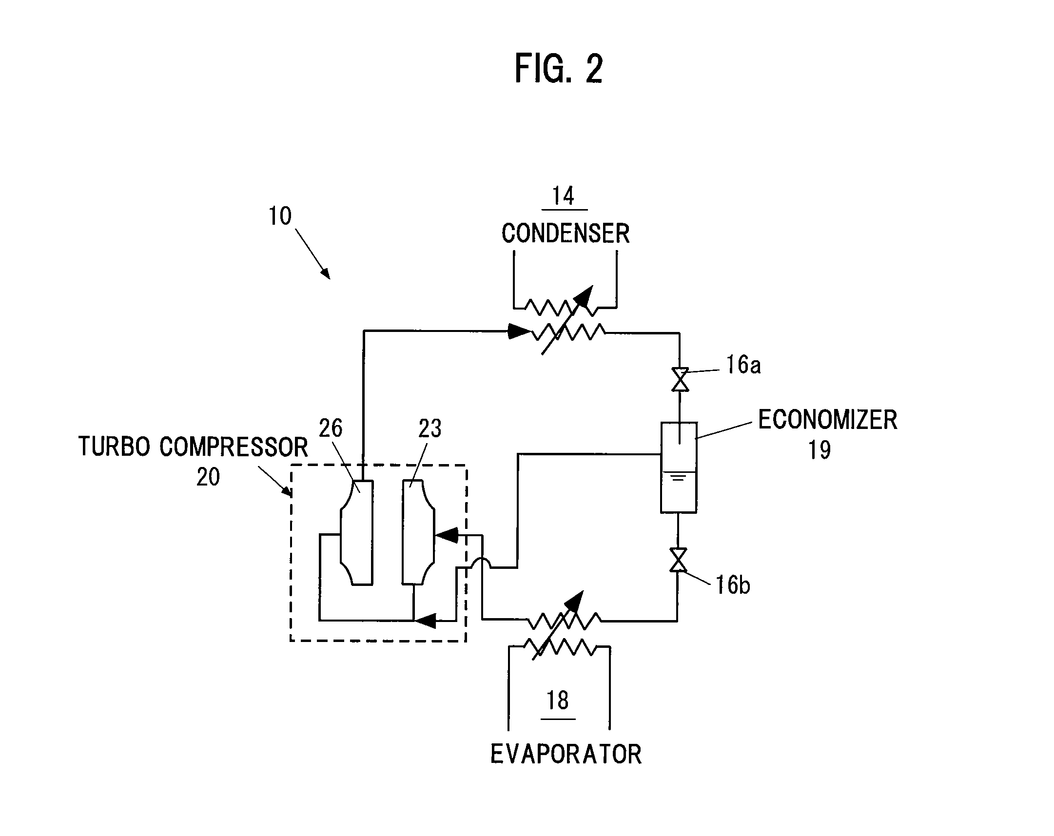
[0048]FIG. 2 is a view showing an arrangement of a refrigerating circuit of a turbo refrigerator 10 to which a turbo compressor in accordance with the present invention is applied.

[0049]In FIG. 2, the turbo refrigerator 10 is provided with a turbo compressor 20, a condenser 14, expansion valves 16a and 16b, an evaporator 18 and an economizer 19.

[0050]The turbo compressor 20 is a two-stage turbo compressor provided with a first stage centrifugal impeller 23 and a second stage centrifugal impeller 26, wherein the coolant gas is compressed by the first stage centrifugal impeller 23 on the upstream side, introduced into the second stage centrifugal impeller 26 and further compressed, and thereafter delivered to the condenser 14.

[0051]The condenser 14 cools and liquefies the compressed high-temperature and high-pressure coolant gas into a coolant liquid.

[0052]The expansion valves 16a and 1...

second embodiment

[0102]The description will be given below of a turbo compressor 20 in accordance with a second embodiment of the present invention.

[0103]FIG. 6 is a partly enlarged cross sectional view showing a structure of the turbo compressor 20 in accordance with the second embodiment.

[0104]As shown in FIG. 6, in accordance with the present embodiment, the bearings 50 are bearings commonly supporting the radial load and the thrust load applied to the rotating shaft 28, and comprise deep groove ball bearings 54 and 55 supporting the rotating shaft 28 at two axially spaced apart supporting positions, respectively. However, the deep groove ball bearing may be provided at any one of two supporting positions, and the other kind of bearing (for example, cylindrical roller bearing) may be provided at the other of the supporting positions, to support the rotating shaft 28.

[0105]In the bearings 50, the deep groove ball bearing 54 (hereinafter, refer to as “first deep groove ball bearing” as well) suppor...

third embodiment

[0112]The description will be given below of a turbo compressor in accordance with a third embodiment of the present invention. FIG. 7 is a partly enlarged cross sectional view showing a structure of the turbo compressor 20 in accordance with the third embodiment.

[0113]As shown in FIG. 7, in the present embodiment, the bearings 50 are constituted by the cylindrical roller bearings 51 and 52 supporting the radial load applied to the rotating shaft 28 at respective two axially spaced supporting positions, respectively, and the thrust bearing 53 supporting the thrust load applied to the rotating shaft 28.

[0114]With regard to axial positions of the rotating shaft 28, all of these bearings are arranged at the positions on the opposite side from the first stage centrifugal impeller 23 with respect to the second stage centrifugal impeller 26 in the axial direction (left positions from the second stage centrifugal impeller 26 in this drawing).

[0115]Further, as shown in FIG. 7, the speed inc...


PUM


Abstract

A first centrifugal impeller and a second centrifugal impeller are arranged in such an orientation that back sides of the first centrifugal impeller and the second centrifugal impeller face to each other. Bearings are cylindrical roller bearings and a thrust bearing. The cylindrical roller bearings are arranged at two axially spaced supporting positions respectively, and support a radial load applied to the rotating shaft. The thrust bearing supports a thrust load applied to the rotating shaft.

Description

BACKGROUND OF THE INVENTION[0001]1. Technical Field of the Invention[0002]The present invention relates to a turbo compressor, and more particularly to a turbo compressor in which a service life of bearings is elongated and a critical speed of a rotating shaft is improved.[0003]2. Description of Related Art[0004]In a refrigerating machine, there is employed a centrifugal compressor, so-called turbo compressor, for compressing a coolant gas serving as a working fluid to bring the compressor in the high temperature and high pressure state.[0005]Meanwhile, in the compressor, if a compression ratio is higher, a discharge temperature of the compressor becomes higher and a volumetric efficiency is lowered. Particularly, if the evaporation temperature becomes lower, the compression ratio becomes higher, and accordingly, there is a case that a compressing operation is divided into two stages, three stages or more stages. The turbo compressor in which the compressing operation is executed by...

Claims


Application Information

Patent Timeline
Patent Type & Authority Applications(United States)
IPC IPC(8): F01D3/04
CPCF04D17/12F04D25/16F04D29/059F25B1/053F25B1/10F25B2400/13F25B2400/23
Inventor TAKAHASHI, TOSHIOHIRATA, YUTAKAKOBAYASHI, KAZUOKURIHARA, KAZUAKIODA, KENTARO
Owner DAIKIN IND LTD
Why Eureka
Try Eureka