Dynamoelectric machine having encapsulated coil structure with one or more of phase change additives, insert molded features and insulated pinion

a technology of phase change additives and dynamoelectric machines, which is applied in the direction of magnetic circuit rotating parts, stator/rotor bodies, and shape/form/construction of magnetic circuits, etc. it can solve the problems of difficult to achieve consistent process, large ovens, and difficult to perform reliable, consistent trickle process, etc., to achieve the effect of increasing the critical speed of the armature and increasing the stiffness

Inactive Publication Date: 2005-12-22
BLACK & DECKER INC
View PDF99 Cites 5 Cited by
  • Summary
  • Abstract
  • Description
  • Claims
  • Application Information

AI Technical Summary

Benefits of technology

[0021] In an aspect of the invention, an armature for an electric motor has an armature shaft having a lamination stack thereon. The armature shaft and lamination stack are insert molded in thermally conductive plastic. In an aspect of the invention, the plastic increases stiffness and thus increases the critical speed of the armature. In an aspect of the invention, the mass of plastic, its distribution, or both are varied to adjust the spinning inertia of the armature. In another aspect of the invention, the geometry of the plastic, it mechanical properties, or both are varied to adjust the resonant frequency (critical speed) of the armature.

Problems solved by technology

The process of applying the trickle resin is a somewhat difficult process to manage to obtain consistent results.
It also has a number of drawbacks, not the least of which is the cost and difficulty of performing it with reliable, consistent results.
Initially, the trickle process requires the use of a relatively large and expensive oven to carefully preheat the partially assembled armatures to relatively precise temperatures before the trickle resin can be applied.
It has proven to be extremely difficult to achieve consistent, complete flow of the trickle resin through the slots in the lamination stack.
As such, it is difficult to achieve good flow inbetween the magnet wires with the trickle resin.
Further complicating the manufacturing process is that the trickle resin typically has a short shelf life, and therefore must be used within a relatively short period of time.
This serves to further increase the manufacturing cost and complexity of the armature.
Still another drawback with the trickle process is the relatively high number of armatures which are often rejected because of problems encountered during the process of applying the trickle resin to an otherwise properly constructed armature.
Such problems can include contamination of the commutator of the armature by the trickle resin during the application process, as well as uneven flow of the trickle resin if the pump supplying the resin becomes momentarily clogged.
Accordingly, the difficulty in controlling the trickle resin application process produces a relatively large scrap rate which further adds to the manufacturing cost of electric motors.
This can result in problems in dissipating the heat generated in the coils 54 during the operation of the motor in which armature 40 is used.
First, the planes in which the material are removed are located within the length of the lamination stack and thus are relatively distant from the bearing planes where the imbalance forces are transmitted to the rest of the product.
Second, removal of material from the motor's active iron core (lamination stack) has a negative effect on performance, particularly, torque ripple.
Third, balancing by removing material from the surface of the lamination stack requires that the tooth tops of the lamination stack be thicker than needed for spreading magnetic flux.
This non-homogeneity presents a more difficult computation to the dynamic balancing machine that must decide how much material to remove and where to remove it from.
Consequently, the dynamic balance machines often must make repetitive corrective passes during which even more iron is removed from the lamination stack, further reducing performance.
Such prior art coil stays have certain undesirable characteristics.
Second, the poor thermal conductivity of the coil stay material limits the amount of heat that can be transferred to the surface of lamination stack 12.
However, using a larger size magnet wire to wind the magnet wires would typically require larger slots to accommodate the required number of turns of the larger size magnet wire, which in turn would require a larger lamination stack.

Method used


Image

  • Dynamoelectric machine having encapsulated coil structure with one or more of phase change additives, insert molded features and insulated pinion
  • Dynamoelectric machine having encapsulated coil structure with one or more of phase change additives, insert molded features and insulated pinion
  • Dynamoelectric machine having encapsulated coil structure with one or more of phase change additives, insert molded features and insulated pinion

Examples


Embodiment Construction

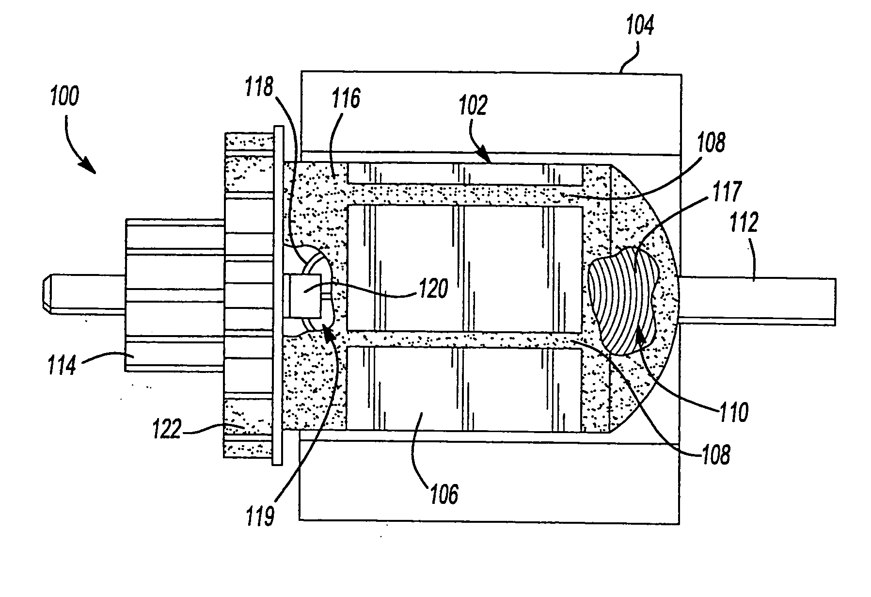
[0078] Referring now to FIG. 5, a motor 100 in accordance with a preferred embodiment of the present invention is disclosed. The motor 100 includes an armature 102 and a stator 104, the stator being illustrated in highly simplified fashion. The armature 102 incorporates a lamination stack 106 having a plurality of longitudinal slots 108 arranged circumferentially therearound. A plurality of magnet wires 110 are wound in the slots 108 to form a plurality of coil windings having end coils 117. An armature shaft112 extends coaxially through the lamination stack 106 and has disposed on one end thereof a commutator 114. A thermally conductive plastic 116 is injection molded over the armature 102 so that the plastic flows into and through each of the slots 108. The thermally conductive plastic 116 is applied by placing the armature 102 in a suitable injection molding tool and then injecting the thermally conductive plastic 116 under a suitably high pressure into the molding tool. The ther...


PUM

PropertyMeasurementUnit
dielectric strengthaaaaaaaaaa
temperatureaaaaaaaaaa
thermally conductiveaaaaaaaaaa

Abstract

An electric motor has an armature and a stators. The armature has a lamination stack having slots therein. An internal shaft extends coaxially through the lamination stack. A plurality of magnet wires are wound in the slots of the lamination stack. A commutator is disposed on the armature shaft to which ends of the magnet wires are electrically coupled. The internal is shaft coupled to an external pinion and bearing journal by an insulated coupling. The magnet wires are at least partially encased in thermally conductive plastic. The magnet wires can have a layer of heat activated adhesive that is activated when the plastic is molded. Slots in the lamination stack can include slot liners formed of thermally conductive plastic. A fan can be formed when the thermally conductive plastic is molded to encapsulate the magnet wires. A power tool has the electric motor.

Description

CROSS-REFERENCE TO RELATED APPLICATIONS [0001] This application is a divisional of U.S. patent application Ser. No. 10 / 616,573 filed Jul. 10, 2003, which is a continuation-in-part of U.S. patent application Ser. No. 10 / 365,065 filed on Feb. 12, 2003, which is a divisional of U.S. patent application Ser. No. 09 / 836,517 filed on Apr. 17, 2001, which is a continuation-in-part of U.S. patent application Ser. No. 09 / 756,959 filed Jan. 9, 2001. U.S. Ser. No. 10 / 616,573 and this application claim the benefit of U.S. Provisional Application No. 60 / 395,251 filed on Jul. 12, 2002.TECHNICAL FIELD [0002] This invention relates to dynamoelectric machines, and more particularly to a dynamoelectric machine having a coil structure encapsulated with a thermally conductive plastic. BACKGROUND OF THE INVENTION [0003] Dynamoelectric machines are machines that generate electric power or use electric power. Common types of dynamoelectric machines are alternators, generators, and electric motors. [0004] E...

Claims


Application Information

Patent Timeline
Patent Type & Authority Applications(United States)
IPC IPC(8): H01R39/14H01R39/32H01R39/52H02K1/04H02K1/30H02K1/32H02K3/12H02K3/30H02K3/34H02K3/46H02K3/48H02K3/487H02K3/50H02K3/51H02K5/08H02K7/04H02K9/06H02K9/20H02K9/22H02K13/00H02K13/04H02K15/12H02K15/16H02K23/00
CPCH01R39/14Y10T29/49011H02K1/30H02K1/32H02K3/12H02K3/30H02K3/345H02K3/46H02K3/48H02K3/487H02K3/50H02K3/51H02K5/08H02K7/04H02K9/06H02K9/20H02K9/22H02K13/006H02K13/04H02K15/12H02K15/165H02K23/00Y10T29/49078Y10T29/49012Y10T29/49071Y10T29/49075Y10T29/49009H01R39/32
Inventor DU, HUNG T.WEST, JOSHUA F.SELL, MICHAEL R.WALTER, RICHARD T.
Owner BLACK & DECKER INC
Why Eureka
Try Eureka