Portal access device with removable sharps protection

a technology of portability and protection, applied in the direction of intravenous devices, other medical devices, infusion needles, etc., can solve the problems of accidental injury, unnecessarily splattering around, and contaminated fluid at the tip of the needle may adhere to the well,

Active Publication Date: 2007-06-28
SMITHS MEDICAL ASD INC
View PDF37 Cites 162 Cited by
  • Summary
  • Abstract
  • Description
  • Claims
  • Application Information

AI Technical Summary

Benefits of technology

[0021] It is therefore an objective of the present invention to provide a portal access device that alleviates the need to reinsert a sharp cannula in the patient every time there is a need to either remove fluid from, or infuse fluid into, the portal reservoir implanted in the patient.
[0022] It is another objective of the present invention to provide a portal access device which needle insertion portion may be safely removed after the port has been accessed.
[0023] It is yet another objective of the present invention to provide a portal access device that allows a medical personnel to readily gain access to a portal reservoir implanted in a patient to clean out any obstruction that might occlude the flow of fluid into or out of the portal reservoir.
[0024] It is a further objective of the instant invention to provide a needle insertion device configured to prevent the tip of the contaminated needle or cannula from touching any part of the base of the device, and from being exposed to the environment or viewed by the patient or the user once the sharp cannula is withdrawn from the infuser portion of the portal access device.

Problems solved by technology

As with the use of any needle or sharps instruments, there is always a chance that the user, or a bystander, may be accidentally pricked by the contaminated needle when it is removed from the patient.
Such accidental injury may well be serious as the tip of the needle is contaminated with the fluid from the patient.
Even though surrounded by a dam, the tip of the needle nonetheless is exposed to the environment and viewable by the patient, and there is a remote chance that contaminated fluid at the tip of the needle may adhere to the well, or may be splattered unnecessarily around the area of the well or beyond.
This repeated insertion of a needle to the patient tends to cause discomfort, at the very least, to the patient.

Method used


Image

  • Portal access device with removable sharps protection
  • Portal access device with removable sharps protection
  • Portal access device with removable sharps protection

Examples


first embodiment

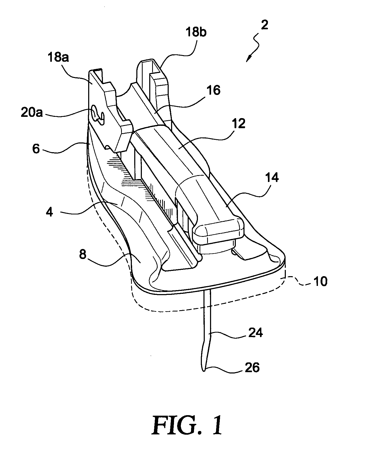
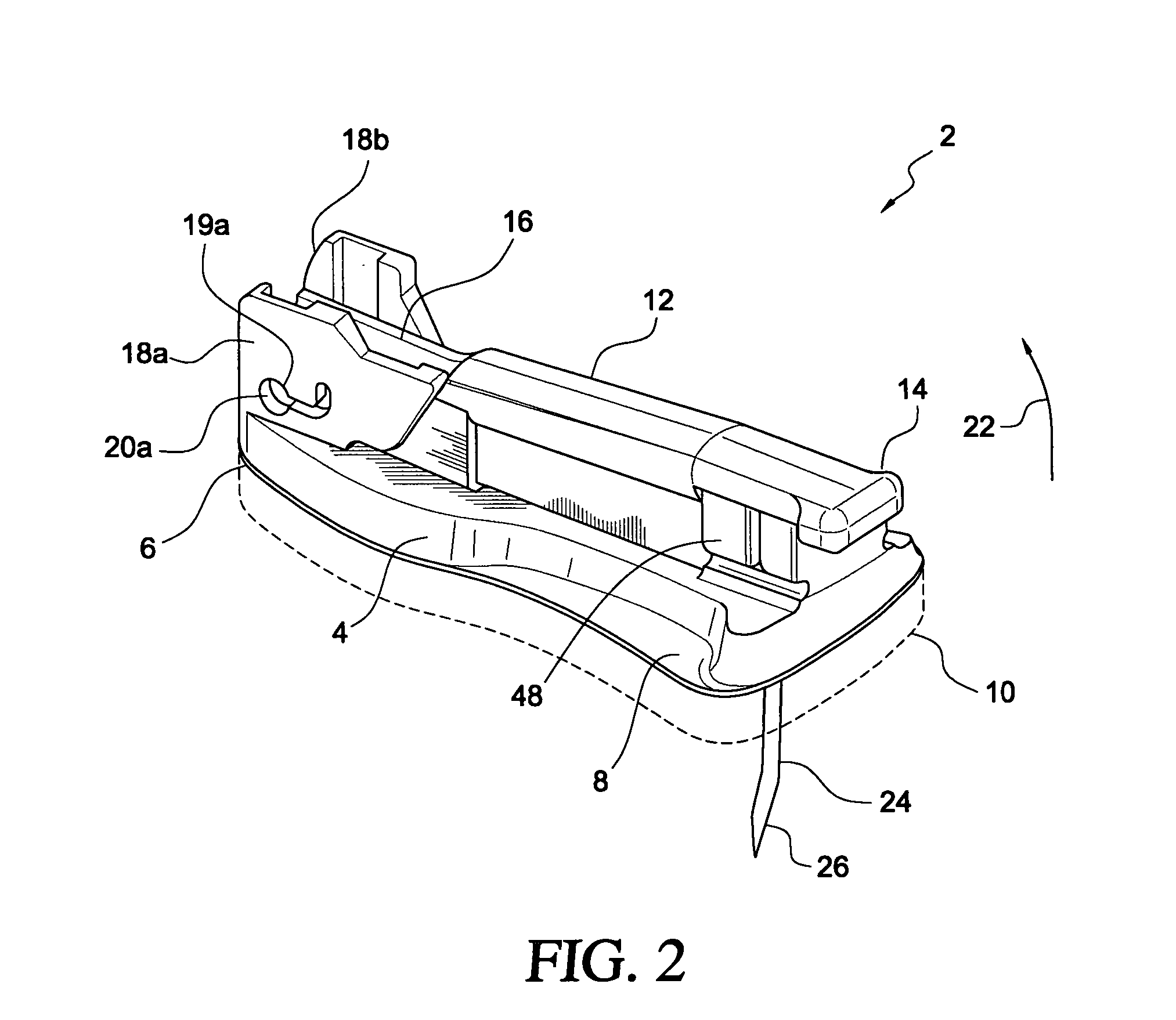
[0038] the safety needle inserter device component of the instant invention is shown in FIGS. 1-4. As shown, the safety needle inserter 2 has a base 4 that has a distal portion 6 and a proximal portion 8. A foam pad or layer 10 coated with an adhesive for adhering base 4 to the patient may be mounted to the underside, or the lower surface, of base 4. An arm having a first end 14 and a second end 16 is hingedly connected to two uprights 18a and 18b, respectively, at distal portion 6 of base 4. Two lugs 19, one at each side of second end 16 of arm 12, are movably journaled to the respective guide holes 20a and 20b of the respective uprights 18a and 18b, to thereby hingedly and movably connect arm 12 to base 4. Only lug 19a is shown in FIG. 2. When uplifted in the direction as indicated by directional arrow 22, arm 12 is pivotally moved, via its second end 16, in an upward direction relative to base 4.

[0039] A needle, or sharp cannula 24, is mounted to the underside of arm 12, at its f...

second embodiment

[0044]FIG. 5 is an illustration of the safety needle inserter of the instant invention. Other than the overall look of the safety needle inserter and the various parts of the locking mechanisms which coact to lock arm 12 in place relative to base 4, the safety needle inserter of the FIG. 5 embodiment functions in the same way as the embodiment shown in FIGS. 1-4. The components that are the same as those of the earlier disclosed embodiment are labeled the same.

[0045] As shown more clearly by the partial cut-away view, the tip 26 of sharp cannula 24, when withdrawn from the portal reservoir and the patient, is maintained within a bore 42 that is formed at the proximal portion 8 of base 4. As shown, bore 42 is defined between opening 44 at the underside or lower surface of base 4 and an opening 44a at the upper side or upper surface 46 of base 4. A dam 48 extends from proximal portion 8 of base 4 and serves as an additional safety feature to ensure that the tip 26 of cannula 24 could ...

third embodiment

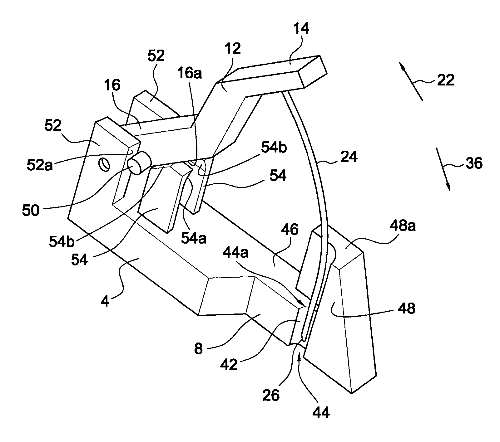
[0047] the safety needle inserter of the instant invention is shown in FIGS. 6-8. This embodiment is a modification of the simplified embodiment shown in FIG. 5 in that uprights 54 have been reconfigured to allow additional flexibility by the adding of a notch 56 thereto. As a consequence, when arm 12 is pulled upwards along the direction as indicated by directional arrow 22, each of uprights 54 would tend to flex away, until the underside 16a of arm 12 clears the top edge 54b of the respective uprights 54. At which time, uprights 54 will return to their respective memorized original positions so as to move upper surfaces 54b of uprights 54 under the bottom surface 16a of arm 12 and more specifically those surfaces of the bosses 52, or areas proximate thereto, to thereby prevent downward movement of arm 12 along the direction as indicated by directional arrow 36.

[0048] Further, similar to the embodiment shown in FIGS. 1-4, respective grooves or recesses 34 are provided at the uprigh...


PUM


Abstract

A portal access device that is adapted to provide long term access to a port implanted in a patient has two major components, an infuser assembly and a safety needle insertion device. The infuser assembly has an infuser housing that can be configured into a specific shape, for example a dome. A blunt cannula is attached to and extends downwardly from the underside of the infuser housing. Also connected to the infuser housing, preferably at a side thereof, is a tubing or catheter. The safety needle inserter assembly has a base having a proximal portion that is configured to form fit over the infuser housing. At the distal portion of the base uprights are provided so that a second end of an arm, to which first end a needle or a sharp cannula is connected, may be movably and hingedly connected to the base. The sharp cannula extends from the underside of the proximal end of the arm and passes through the base by way of a bore formed at the proximal portion of the base. The bore is defined between an opening at the underside of the base and an opening at the upper surface of the base. Locking mechanisms are provided at the base uprights and the distal end of the arm so that when the arm is moved away from the base, and as the distal end of the arm pivots about the uprights, the respective locking mechanisms provided at the arm and the base would coact to lock the arm in place, to thereby maintain the tip of the needle within the bore formed in the base. To use, the safety needle inserter is placed over the infuser assembly, with the sharp cannula extending through the infuser housing and axially mating with the blunt cannula of the infuser assembly, but with the tip of the sharp cannula protruding beyond the tip of the blunt cannula. The combined needle inserter/infuser assembly is pressed down onto the skin surface of the patient so that the combination sharp/blunt cannulas penetrate the patient and puncture the self-sealing septum of a portal reservoir implanted in the patient. Once the safety needle inserter is removed from the infuser assembly, with the infuser housing septum being self-sealing, a closed fluid communication path is established between the portal reservoir and a fluid store that may be connected to the catheter of the infuser assembly. Long term access of the implanted portal reservoir is thereby achieved.

Description

FIELD OF THE INVENTION [0001] The present invention relates to a device for accessing a portal reservoir, and more particularly a portal access device that combines long term accessing of a portal reservoir with sharps protection. BACKGROUND OF THE INVENTION [0002] Long term intravenous therapy to a patient oftentimes requires that a portal reservoir (also may be referred herein as port or portal) be implanted to the patient. The medicament stored in the port is fed slowly to the patient via a catheter connected to the portal. To refill the portal, conventionally a needle is inserted through the skin of the patient into a septum of the portal so that the portal may be refilled with the desired medicament. As with the use of any needle or sharps instruments, there is always a chance that the user, or a bystander, may be accidentally pricked by the contaminated needle when it is removed from the patient. Such accidental injury may well be serious as the tip of the needle is contaminat...

Claims


Application Information

Patent Timeline
Patent Type & Authority Applications(United States)
IPC IPC(8): A61M31/00
CPCA61M5/158A61M2005/1581A61M2005/1585
Inventor MICHELS, LESTER D.BELING, WILLIAM L.TRAVIS, RONALD G.
Owner SMITHS MEDICAL ASD INC
Why Eureka
Try Eureka