
Brush belt

a belt and brush technology, applied in the field of brush belts, can solve the problems of complicated belt body production and relatively rapid contamination of brush belts

Inactive Publication Date: 2007-07-05
KRATZENFAB MEHLHORN
View PDF4 Cites 4 Cited by
  • Summary
  • Abstract
  • Description
  • Claims
  • Application Information

AI Technical Summary

Benefits of technology

[0005]It is therefore an object of the invention to provide a brush belt of the type described above, in which the production is simplified and at the same time, contaminations are reliably avoided.
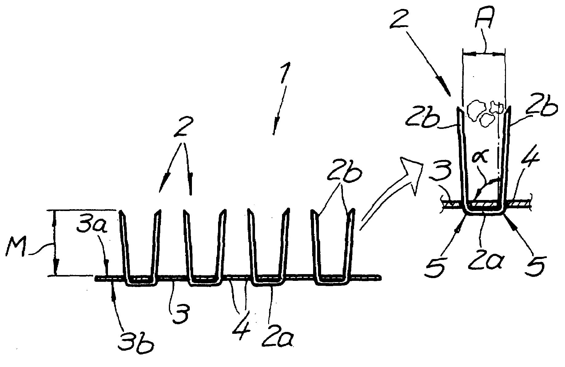
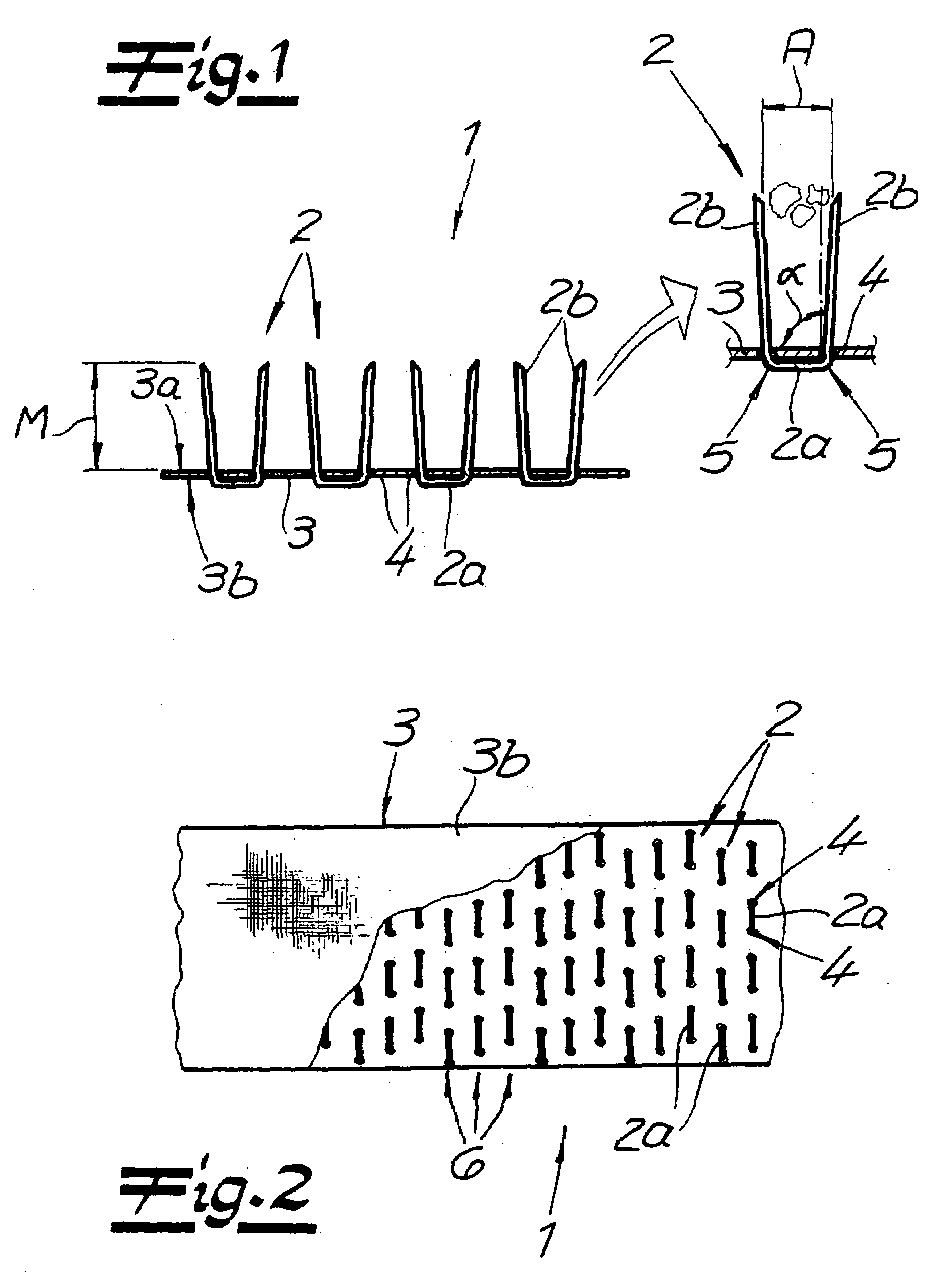
[0006]This object is accomplished by a brush belt having at least one bristle anchored in the belt body in a U-shaped configuration. Each bristle has a crosspiece as the U base and two treatment legs as U shanks. The bristle is, as usual, a thick, stiff (artificial) hair that has at least one plastic sheath. Preferably it is produced entirely from plastic. However, the bristle can also be equipped with a core of steel, for example, and the necessary plastic sheath. In this way, even sensitive surfaces can be cleaned and worked with the brush belt implemented in this manner.
[0011]Because the treatment legs stand up almost vertically on the surface of the belt body in their anchored state, in contrast to the state of the art, there is no risk that dirt particles, foreign bodies, etc., that are loosened from a surface using the brush belt will remain hanging between the bristles and essentially plug up the interstices. In order to further increase this advantage, the two treatment legs of the bristle are each disposed at a distance relative to one another that is adapted to the dirt particles, foreign objects, etc., that are to be loosened from a surface. This means that the distance between the two treatment legs will be variably adjusted to the application of the brush belt and the size of the loosened dirt particles or foreign bodies, during the production process of the U-shaped bristles made of plastic. The same also holds true, of course, for the arrangement of the passage openings in the belt body.
[0012]The belt body is preferably produced from a woven textile in which the passage openings are made in a uniform distribution. This is because such a woven textile does not tend to splice open and makes a solid surface, closed in the finished state, available even when passage openings have been made in it. Furthermore, the passage openings can easily be made in such a woven textile, with corresponding needle tools, particularly in a variable distribution.
[0016]It is always guaranteed that the treatment legs, which stand more or less vertically on the top of the belt body, produce a uniform bristle pattern with treatment legs that are essentially at equal distances from one another. As a result, interstices of practically equal size are available between the treatment legs, in which the loosened dirt particles or foreign bodies find hardly any hold. This is all the more true if the treatment legs are adapted to the size of the particles or foreign bodies in question, in terms of the distance between them. All of this is possible while assuring gentle surface treatment.

Problems solved by technology

This has the result that the brush belt can become contaminated relatively quickly when cleaning surfaces, because loosened dirt particles or foreign bodies become lodged between the bristles, which project in a V shape from the belt body.
Furthermore, the production of the belt body is complicated.

Method used


Image

  • Brush belt
  • Brush belt

Examples


Embodiment Construction

[0021]Referring now in detail to the drawings, the figures show a brush belt 1, which has several bristles 2, which are anchored in a belt body 3. Bristles 2 are produced completely from plastic such as polyamide (PA), acryl nitrile butadiene styrene (ABS), polycarbonate (PC), polyethylene (PE), polyethylene terephthalate (PET), polypropylene (PP), etc. Aside from the aforementioned thermoplastics, bristles 2 made of duroplastics are fundamentally also possible.

[0022]Bristles 2 are each configured in U shape, with a crosspiece 2a as the U base and two treatment legs 2b as the U shanks, in each instance. To produce the bristles 2, a standard injection-molding method can be used, which produces the bristles 2 in their form as shown right from the start. Then it is possible to place a supply of U-shaped bristles 2 into a magazine and to introduce them into belt body 3 using a punch.

[0023]Alternatively to this, however, bristles 2 can also be produced from a single strand of plastic tha...


PUM


Abstract

A brush belt has a belt body and at least one bristle anchored in the belt body. The bristle has at least one plastic sheath. The bristle is U-shaped with a crosspiece as the U base and two treatment legs as U shanks.

Description

BACKGROUND OF THE INVENTION[0001]1. Field of the Invention[0002]The invention relates to a brush belt having a belt body and at least one bristle anchored in the belt body, which bristle has at least one plastic sheath.[0003]2. The Prior Art[0004]Such a brush belt is described in Swiss Patent No. CH 412 793. Such brush belts, having a plastic bristle anchored in the belt body using steel staples, are known from practice. Consequently, each bristle has a more or less V-shaped form at the top of the belt body. This has the result that the brush belt can become contaminated relatively quickly when cleaning surfaces, because loosened dirt particles or foreign bodies become lodged between the bristles, which project in a V shape from the belt body. Furthermore, the production of the belt body is complicated.SUMMARY OF THE INVENTION[0005]It is therefore an object of the invention to provide a brush belt of the type described above, in which the production is simplified and at the same tim...

Claims


Application Information

Patent Timeline
Patent Type & Authority Applications(United States)
IPC IPC(8): A46B3/00
CPCA46B5/06
Inventor MEHLHORN, RAINER
Owner KRATZENFAB MEHLHORN
Learn More