
System, method, and apparatus for frame assembly and building

a frame and housing technology, applied in the field of system, method and apparatus for building frames, can solve the problems of complex and costly prior building designs, large number of prior building designs of this type, and use of relatively complicated means

Inactive Publication Date: 2007-07-05
BOATWRIGHT GARRY
View PDF35 Cites 12 Cited by
  • Summary
  • Abstract
  • Description
  • Claims
  • Application Information

AI Technical Summary

Benefits of technology

[0006] One embodiment of a system, method, and apparatus for forming an A-frame assembly for use in constructing a building, dwelling, or other structure is disclosed. The assembly comprises only five major components, all of which may be formed from square, galvanized steel hollow tubing. The five major components include corner braces, side braces, a top brace, beams, and straight tubing. The straight tubing interconnects the other components to form a triangular frame assembly. The corner braces may be secured with concrete footings or a complete foundation.

Problems solved by technology

Although one of the primary advantages thought to be provided by the A-frame building design concept is that of simplicity and therefore economy, many prior building designs of this type have in fact been complicated and costly.
One characteristic of the type of complexity that is often found in prior art A-frame building designs involves the use of separate frame and roof and wall members.
Many prior art A-frame building designs have also employed relatively complicated means of interconnecting either the frame or the roof and wall members to the underlying floor structure.

Method used


Image

  • System, method, and apparatus for frame assembly and building
  • System, method, and apparatus for frame assembly and building
  • System, method, and apparatus for frame assembly and building

Examples


Embodiment Construction

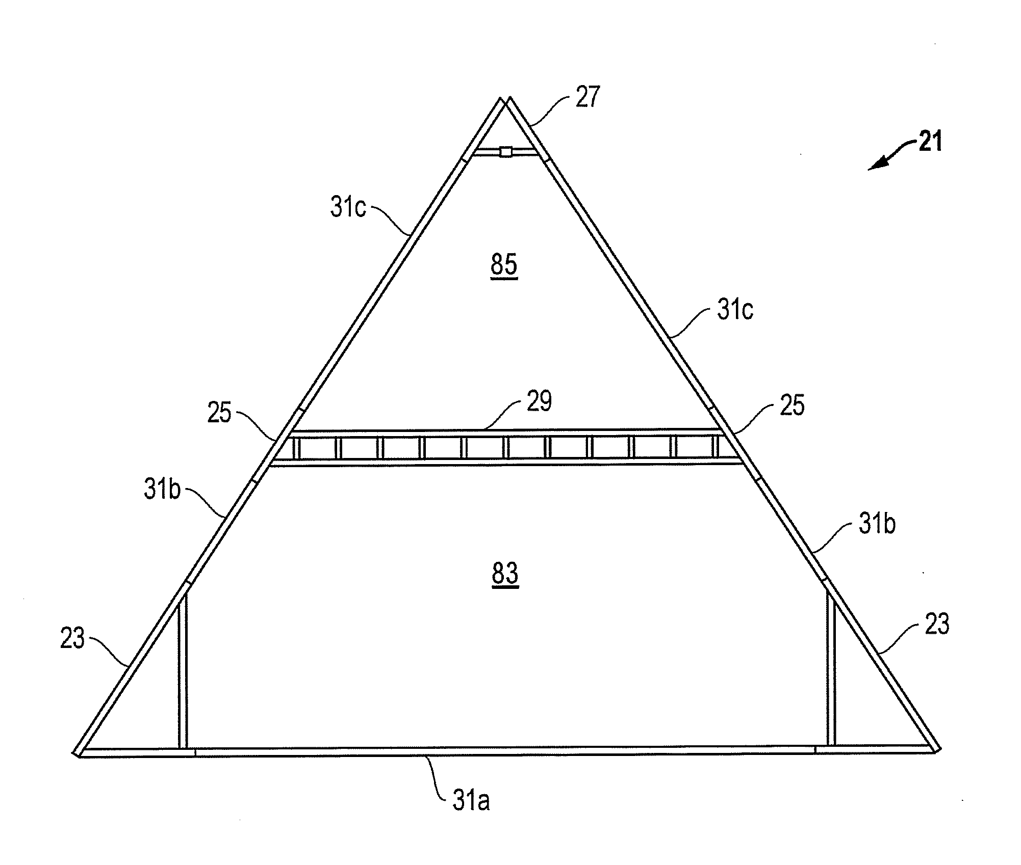
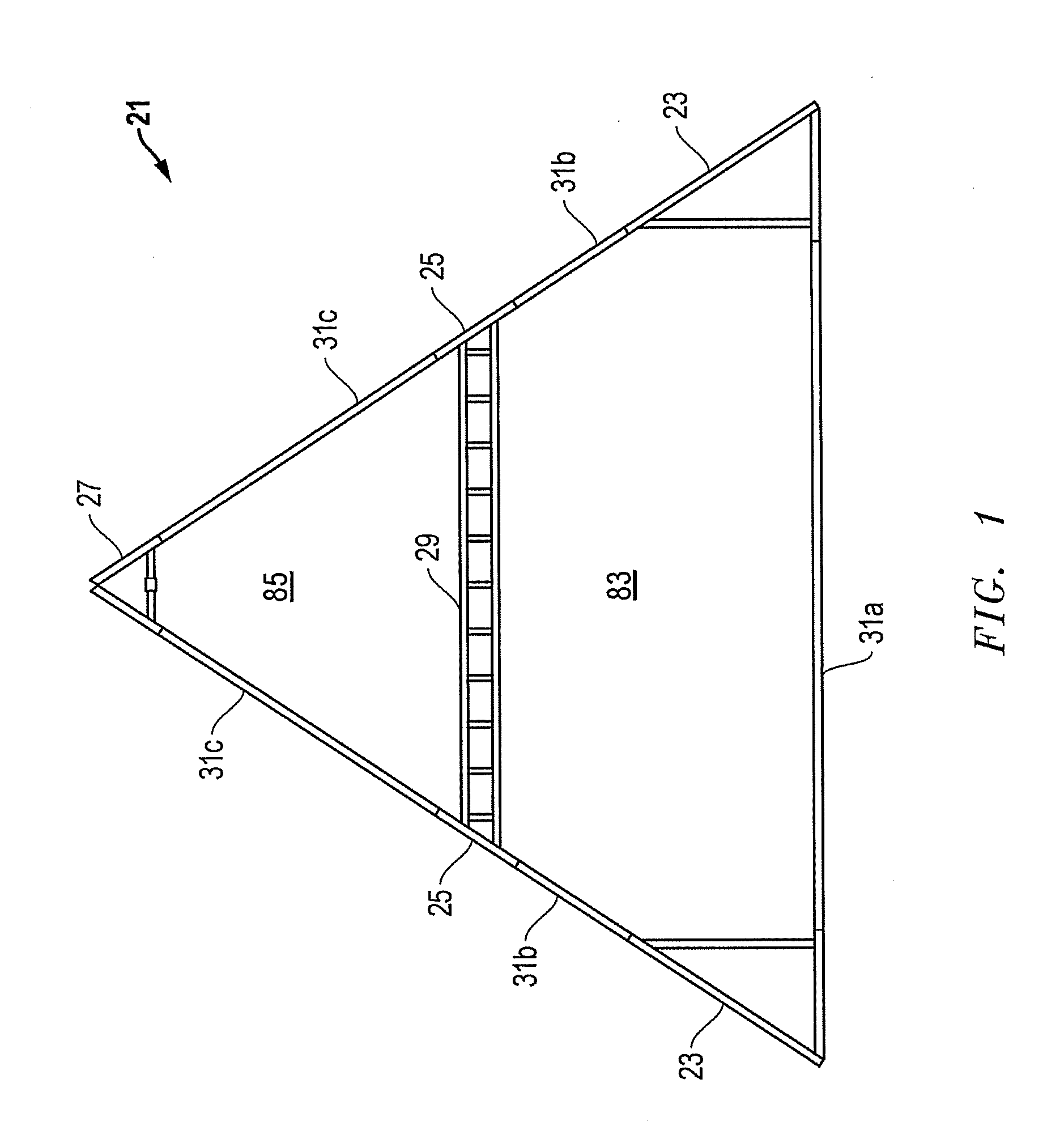
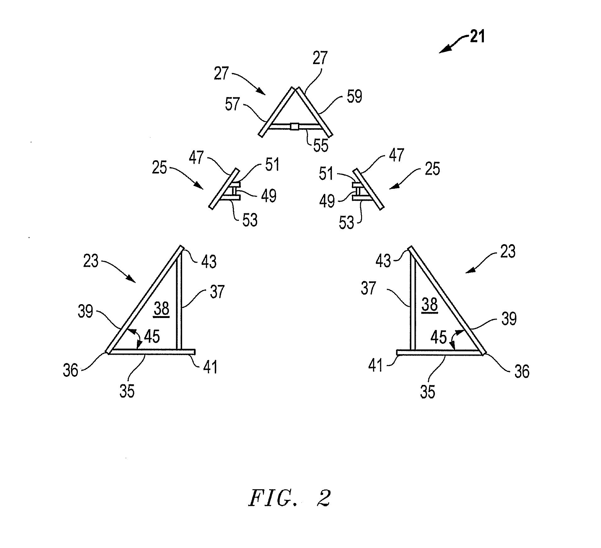
[0029] Referring to FIGS. 1 and 2, one embodiment of a system, method, and apparatus for forming a truss or frame assembly 21 (e.g., an A-frame assembly) for use in constructing a building, dwelling, or other structure is shown. Assembly 21 comprises only five major components, all of which are formed from square, galvanized steel hollow tubing in one embodiment. The five major components include corner brace 23, side brace 25, top brace 27, beams 29, and straight tubing 31.

[0030] The straight tubing 31 is cut to different lengths (see, e.g., lower, middle, and upper pieces 31a, 31b, 31c) and interconnects the other four components to form the triangle-shaped frame assembly 21. The left and right corner braces 23 and side braces 25 are identical, respectively, but oriented in opposite directions. Top brace 27 may be triangular as shown, or rounded as shown in the embodiment shown as top brace 33 in FIG. 3. In one embodiment, the assembled components are joined together with fastene...


PUM


Abstract

An A-frame assembly for constructing a building comprises only five major components that are formed from square, galvanized steel hollow tubing. These components include corner braces, side braces, a top brace, beams, and straight tubing. The straight tubing interconnects the other components to form a triangular frame assembly. The corner braces are secured with concrete footings or a complete foundation. A number of the frame assemblies are arrayed to form the basis of a structure. The frame assemblies are spaced apart from each other, joined with additional square tubing, and include an attic space and service spaces between the corner braces. A roofing structure is secured to the joined frame assemblies to complete the structural phase of the assembly.

Description

[0001] This application claims priority to and the benefit of U.S. Provisional Patent Application No. 60 / 750,970, filed on Dec. 16, 2005, and is incorporated herein by reference.BACKGROUND OF THE INVENTION [0002] 1. Technical Field [0003] The present invention relates in general to a building frame and dwelling built thereon and, in particular, to an improved system, method, and apparatus for an A-frame assembly and dwelling. [0004] 2. Description of the Related Art [0005] In the prior art, a wide variety of A-frame building designs have been proposed. However, the need persists for considerable improvement in the art. Although one of the primary advantages thought to be provided by the A-frame building design concept is that of simplicity and therefore economy, many prior building designs of this type have in fact been complicated and costly. One characteristic of the type of complexity that is often found in prior art A-frame building designs involves the use of separate frame and...

Claims


Application Information

Patent Timeline
Patent Type & Authority Applications(United States)
IPC IPC(8): E04H12/00
CPCE04B1/24E04B2001/0069E04B2001/249E04B2001/2463E04B2001/2472E04B2001/2451
Inventor BOATWRIGHT, GARRY
Owner BOATWRIGHT GARRY
Learn More