System and method of testing liquid crystal display device using dispensing state of liquid crystal dispensing apparatus

liquid crystal dispensing technology, which is applied in the field of system and method of testing the quality of a liquid crystal display device, can solve the problems of increasing the time required to complete the liquid crystal fabrication, reducing the efficiency of fabricating, and using a considerable amount of liquid crystal in the panel b. to achieve the effect of rapid and accurate testing

Inactive Publication Date: 2007-07-05
LG DISPLAY CO LTD
View PDF4 Cites 3 Cited by
  • Summary
  • Abstract
  • Description
  • Claims
  • Application Information

AI Technical Summary

Benefits of technology

[0018]An advantage of the present invention is to provide a liquid crystal dispensing apparatus for directly dispensing liquid crystal onto a glass substrate of a large area including at least one liquid crystal panel.
[0019]Another advantage of the present invention is to provide a system and method of testing a liquid crystal display device, which allow a rapid and accurate test by testing inferiority of a liquid crystal panel on the basis of a dispensed amount measured by a liquid crystal dispensing apparatus.
[0020]Additional features and advantages of the invention will be set forth in the description which follows, and in part will be apparent from the description, or may be learned by practice of the invention. The objectives and other advantages of the invention will be realized and attained by the structure particularly pointed out in the written description

Problems solved by technology

However, there are problems associated with forming a liquid crystal layer using the injection method of the related art.
First, considerable time is used to inject the liquid crystal into the panel 1.
Thus, the use of the liquid crystal injection method results in increased time to complete the liquid crystal fabrication process, thereby reducing fabricating efficiency.
Secondly, use of the liquid crystal injection method increases the consumption of liquid crystal.
H

Method used


Image

  • System and method of testing liquid crystal display device using dispensing state of liquid crystal dispensing apparatus
  • System and method of testing liquid crystal display device using dispensing state of liquid crystal dispensing apparatus
  • System and method of testing liquid crystal display device using dispensing state of liquid crystal dispensing apparatus

Examples


Embodiment Construction

[0041]Reference will now be made in detail to embodiments of the present invention, examples of which are illustrated in the accompanying drawings.

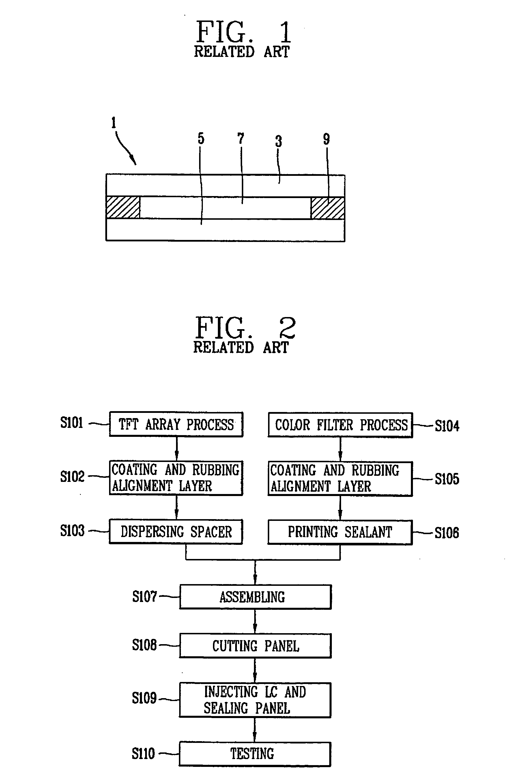
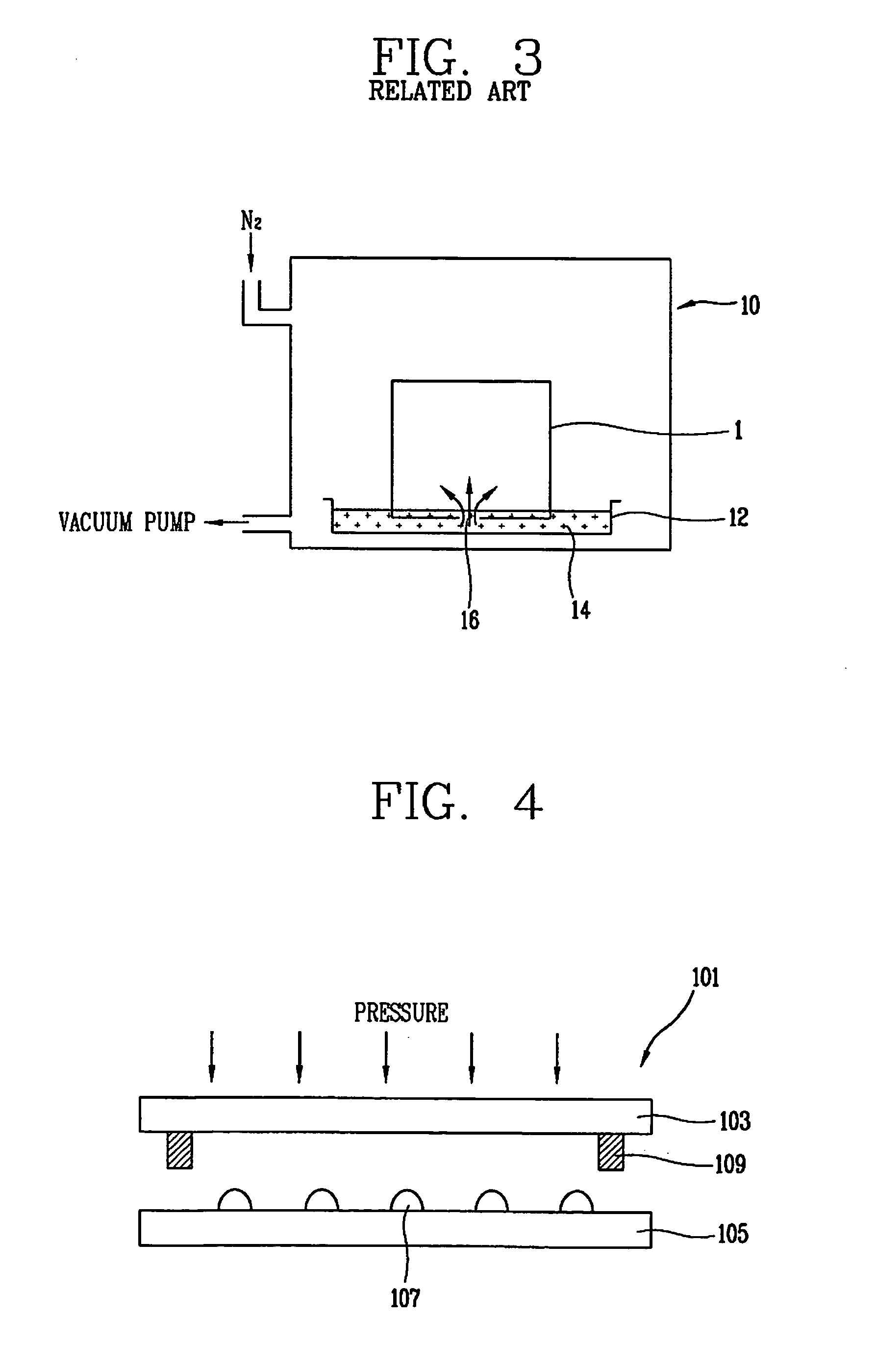
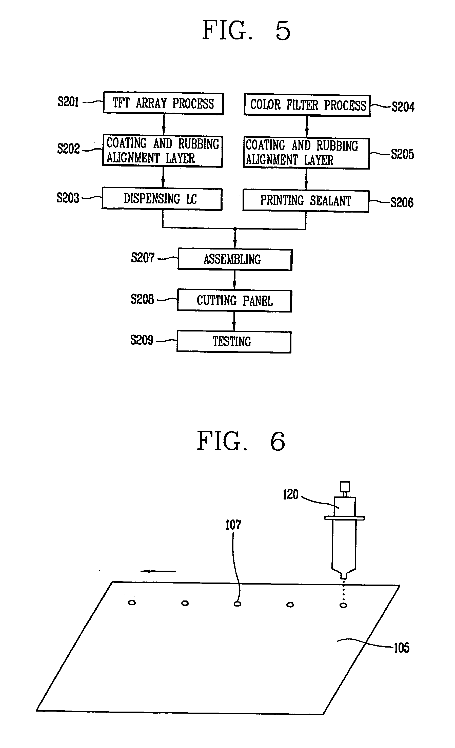
[0042]In order to solve the problems of the related liquid crystal injection methods such as the liquid crystal dipping method or the liquid crystal vacuum injection method, a liquid crystal dispensing method has been recently introduced. The liquid crystal dispensing method is a method for forming a liquid crystal layer by directly dropping the liquid crystal onto the substrates and spreading the dropped liquid crystal over the entire panel by pressing together the substrates during the assembling procedure of the substrates rather than by injecting the liquid crystal into the empty unit panel by the pressure difference between the inner and outer sides of the panel. According to the above liquid crystal dispensing method, the liquid crystal is directly dropped onto the substrate in a short time period so that the liquid crystal layer in...


PUM

PropertyMeasurementUnit
Weightaaaaaaaaaa

Abstract

Disclosed is a method of testing a liquid crystal display device enabling a quick test by determining a test of a liquid crystal panel according to a liquid crystal filling state of the liquid crystal panel. The method includes: checking a liquid crystal filling state of a liquid crystal panel for a defective liquid crystal filling state; and executing a test of a liquid crystal panel having a defective liquid crystal filling state. The process for testing a liquid crystal filling state may include detecting a dispensed amount of liquid crystal dropped using a liquid crystal dispensing apparatus or may include measuring the weight of liquid crystal dropped. Other methods of identifying the filling state of the liquid crystal panel may be used.

Description

[0001]This application claims the benefit of Korean Patent Application No. 10-2005-0134585, filed on Dec. 29, 2005, which is hereby incorporated by reference for all purposes as if fully set forth herein. This application incorporates by reference co-pending application, Ser. No. 10 / 184,096, filed on Jun. 28, 2002 entitled “SYSTEM AND METHOD FOR MANUFACTURING LIQUID CRYSTAL DISPLAY DEVICES FROM LARGE MOTHER SUBSTRATE PANELS” (Attorney Docket Number 8733.666.00); and co-pending application, Ser. No. ______, filed on Jun. 29, 2006, entitled “METHODS OF MANUFACTURING LIQUID CRYSTAL DISPLAY DEVICES” (Attorney Docket Number 8733.1713.00) for all purposes as if fully set forth herein.BACKGROUND OF THE INVENTION[0002]1. Field of the Invention[0003]The present invention relates to a system of testing a liquid crystal display device, and more particularly, to a system and method for testing the quality of a liquid crystal display device.[0004]2. Discussion of the Related Art[0005]With the de...

Claims


Application Information

Patent Timeline
IPC IPC(8): B65B3/26
CPCG02F1/1341G02F1/1309
Inventor BOK, GU-YUN
Owner LG DISPLAY CO LTD
Why Eureka
Try Eureka