Deformable release device for use with downhole tools

a release device and tool technology, applied in the direction of fluid removal, wellbore/well accessories, sealing/packing, etc., can solve the problems of affecting the operation of the release device, the relative difficulty of rotating the setting tool and the adapter kit, and the debris from the release device remaining in the well bore afterward, so as to prevent the accidental detachment of the stinger, prevent the upward movement of the plunger, and minimize the damage to the downhole components

Inactive Publication Date: 2007-07-05
BJ SERVICES CO
View PDF13 Cites 31 Cited by
  • Summary
  • Abstract
  • Description
  • Claims
  • Application Information

AI Technical Summary

Benefits of technology

[0024] In one embodiment, an apparatus is disclosed for selectively releasing a setting tool from a downhole assembly. The apparatus may include means, such as an adapter kit, to connect a stinger to the setting tool. The lower end of the stinger may be connected to a plunger. The apparatus may include means for preventing upwards movement of the plunger with respect to the downhole assembly, such as a deformable device connected to the downhole assembly. The deformable device may be located between the stinger and the plunger preventing the movement of the stinger and the plunger. Alternatively, a portion of the plunger may be sized to prevent the passage of the plunger through a central opening in the deformable device. The stinger and the plunger may be integral or the stinger may include a portion larger than the central opening of the deformable device as would be appre

Problems solved by technology

However, in some situations, such as in horizontal wells, it can be relatively difficult to rotate the setting tool and adapter kit.
Such components fail with the application of a predetermined amount of a tensile or axial force.
One potential problem with using release devices that fail under a designated mechanical force, such as a release stud or shear pin, is that debris from the release device remains in the well bore after the device has released.
Additionally, the debris may accumulate on or in a moving part of a downhole tool possibly causing the downhole tool to malfunction.
A malfunction of the downhole tool increases the normal operating costs of the well.
Another disadvantage of using shear pins, or other m

Method used


Image

  • Deformable release device for use with downhole tools
  • Deformable release device for use with downhole tools
  • Deformable release device for use with downhole tools

Examples


Embodiment Construction

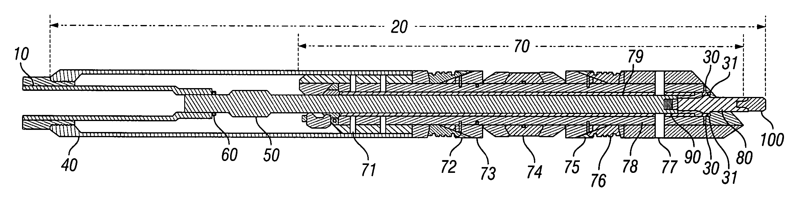
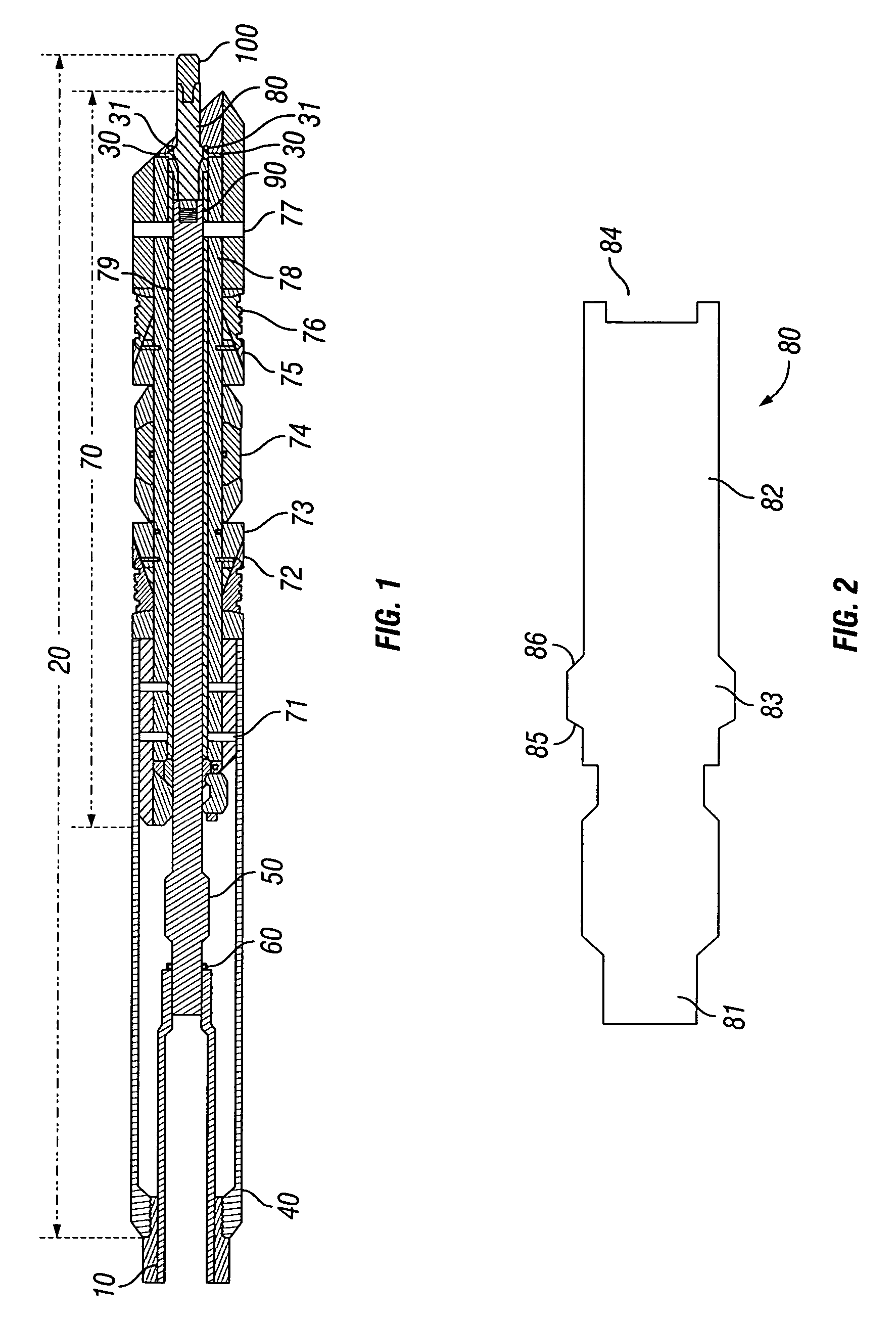
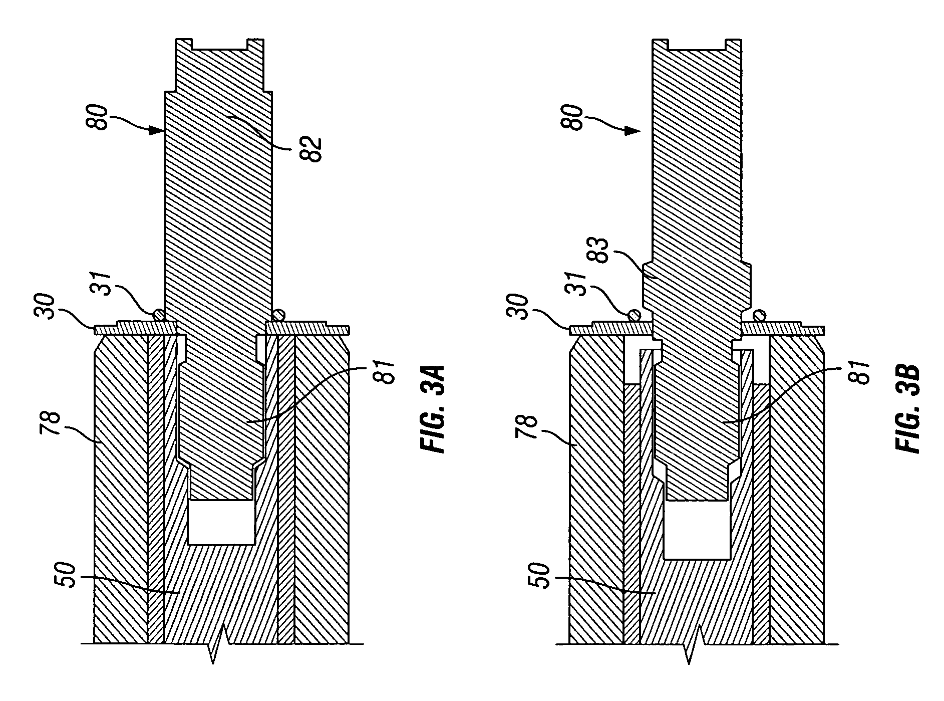
[0036] Illustrative embodiments of the invention are described below as they might be employed in the use of designs for deformable release devices to be used with downhole setting tools. In the interest of clarity, not all features of an actual implementation are described in this specification. It will of course be appreciated that in the development of any such actual embodiment, numerous implementation-specific decisions must be made to achieve the developers' specific goals, such as compliance with system-related and business-related constraints, which will vary from one implementation to another. Moreover, it will be appreciated that such a development effort might be complex and time-consuming, but would nevertheless be a routine undertaking for those of ordinary skill in the art having the benefit of this disclosure.

[0037] Further aspects and advantages of the various embodiments of the invention will become apparent from consideration of the following description and drawi...


PUM


Abstract

A deformable release device is disclosed to be used with downhole setting tools. The deformable release device may provide a releasable detachment to any customary setting tool, such as electric line, hydraulic, hydrostatic, and mechanical setting tools, used to set a downhole packer-type device. The deformable release device allows for the automatic release of downhole setting tools at the application a predetermined force, similar to a shear pin or shear stud. However, since the deformable release device deforms rather than shears or breaks, the releasing device minimizes the debris or remnants of the device left in the wellbore.

Description

CROSS REFERENCE TO RELATED APPLICATION [0001] This application is a Non-provisional application claiming benefit of U.S. Provisional Application Ser. No. 60 / 755,358, entitled, “Deformable Release Device for Use with Downhole Tools,” by Douglas J. Lehr, Gabriel A. Slup, and James Van Lue, filed Dec. 30, 2005, hereby incorporated by reference in its entirety herein.BACKGROUND OF THE INVENTION [0002] 1. Field of the Invention [0003] The present invention relates generally to a release device that may be used with downhole setting tools. Specifically, the release device of the present disclosure deforms to provide a releasable detachment mechanism for a setting tool used to set a downhole tool, such as a Python Frac Plug from BJ Services Company of Houston, Tex. A deformable release device may provide a releasable detachment to any customary setting tool used to set a downhole packer-type device, for example. As would be appreciated by one of ordinary skill in the art having the benefit...

Claims


Application Information

Patent Timeline
IPC IPC(8): E21B33/129
CPCE21B23/06
Inventor LEHR, DOUGLAS J.SLUP, GABRIEL A.VAN LUE, JAMES
Owner BJ SERVICES CO
Why Eureka
Try Eureka