Alternating current detection coil

a detection coil and alternating current technology, applied in the direction of voltage/current isolation, transformers/inductance coils/windings/connections, instruments, etc., can solve the problems of deteriorating detection accuracy, detection error, difficult control of detection error, etc., to improve detection accuracy

Inactive Publication Date: 2007-07-05
MATSUSHITA ELECTRIC WORKS LTD
View PDF5 Cites 38 Cited by
  • Summary
  • Abstract
  • Description
  • Claims
  • Application Information

AI Technical Summary

Benefits of technology

[0011] The present invention is to solve the problem of the conventional arts described above, and an object of the present invention is to provide

Problems solved by technology

However, the cross-section areas surrounded by the forward coil 105 and the backward coil 107 differ according to their coil pitches, thus sensitivity of the detecting is deteriorated.
The external magnetic field is unnecessary for the original current detection, and the detected current from the external magnetic field causes a detection error.
Consequently, the forward coil 105 and the backward coil 107 cannot c

Method used


Image

  • Alternating current detection coil
  • Alternating current detection coil
  • Alternating current detection coil

Examples


Embodiment Construction

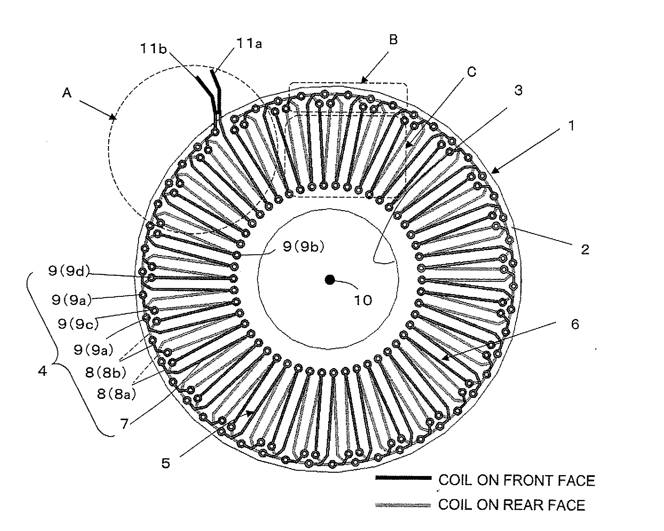
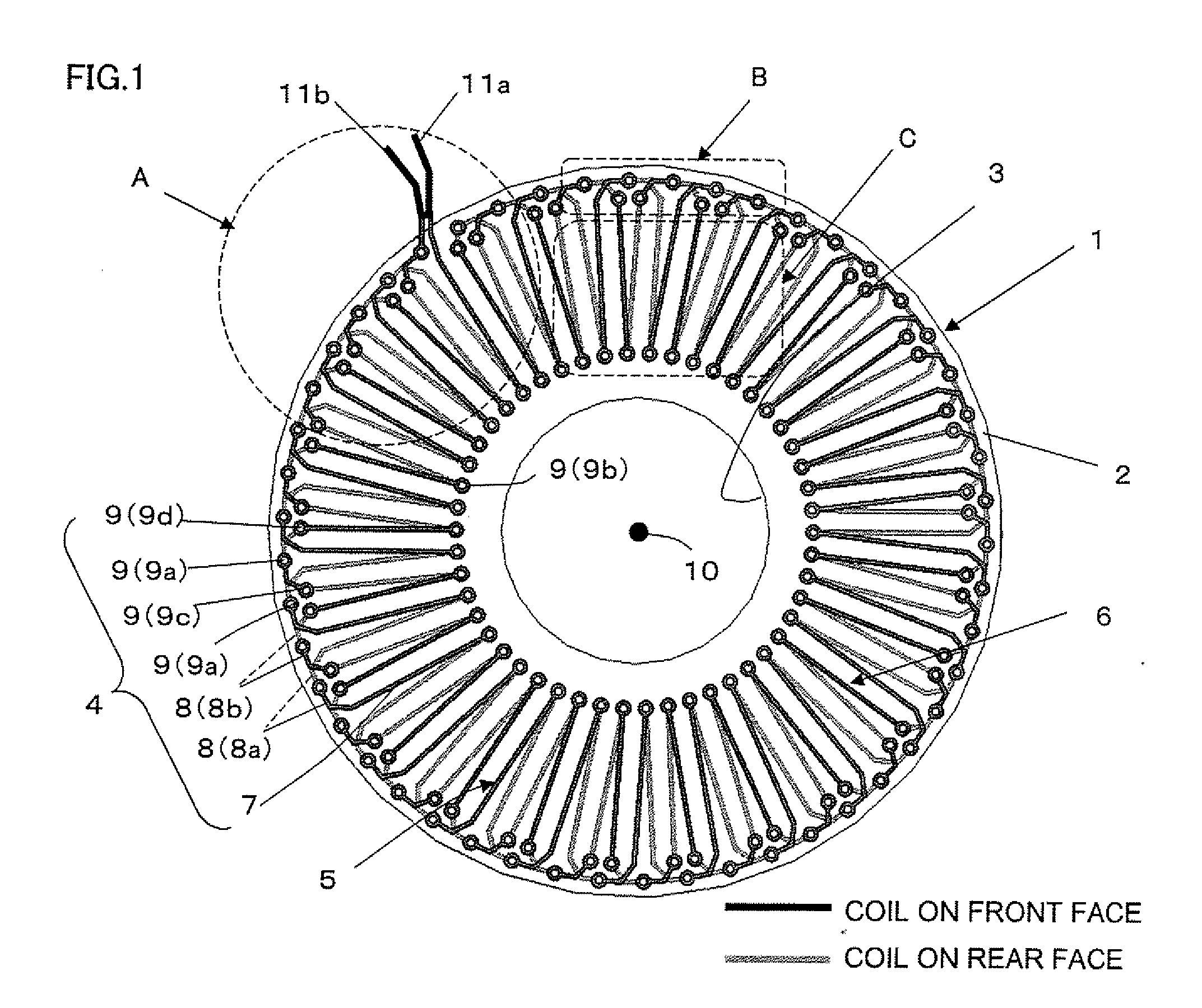
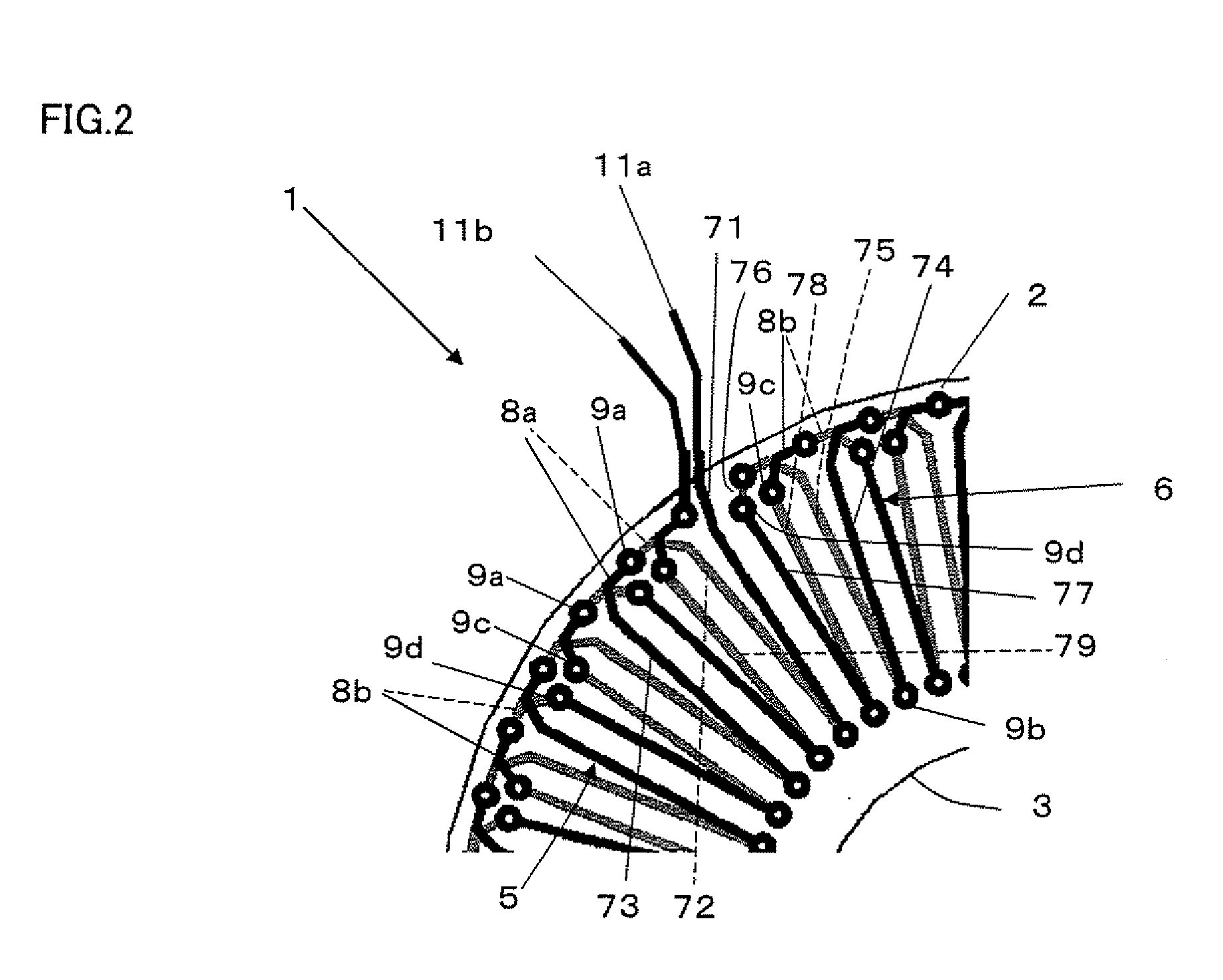
[0052] The alternating current detection coil according to the first preferred embodiment of the present invention is described below with reference to FIGS. 1 to 6D. In FIGS. 1 and 2, an alternating current detection coil 1 (referred to as a detection coil, hereinafter) of the first preferred embodiment comprises a plate-shaped insulating substrate 2 (referred to as a substrate, hereinafter) which is to be a nonmagnetic core of the coil and a toroidal coil 4 formed on the substrate 2. An opening 3 having approximately a circular shape is formed in a center of the substrate 2. The toroidal coil 4 has a forward coil 5 which winds in one direction (a counterclockwise direction) and a backward coil 6 which winds in a reverse direction (a clockwise direction) with returning consecutively from an end of the forward coil 5, and both the forward coil 5 and the backward coil 6 are formed doubly on one substrate 2 and connected consecutively to each other in series.

[0053] The forward coil 5...


PUM


Abstract

The alternating current detection coil is a toroidal coil, and comprises plural radial-line conductors which are formed on a front face and a rear face of a substrate, conductive connection parts and conductive through-holes which connect electrically each end of radial-line conductors, wherein plural winding turns are consecutively formed by a connection of each radial-line conductor on the front face and the rear face respectively, the winding turns comprise a forward coil and a backward coil, and each shape on the front face and the rear face of the radial-line conductors and the conductive connection parts are identical with each other. Consequently, when seen from a thickness direction of the substrate, areas of the forward coil and the backward coil are equal to each other, and an external magnetic field, which does not need to be detected, can be canceled each other by the forward coil and the backward coil, then a current detection accuracy can be improved.

Description

BACKGROUND OF THE INVENTION [0001] 1. Field of the Invention [0002] The present invention relates to an alternating current detection coil which is formed on an insulating substrate to carry out a non-contact detection of a current passing through a branch circuit in a household power distribution board and so on. [0003] 2. Description of the Related Art [0004] A conventional air-core sensor coil used for an alternating current detection is shown in FIGS. 27 and 28 (refer to Japanese Laid-Open Patent Publication No. HEI 06-176947). In these diagrams, a sensor coil 100 comprises a double-sided multilayer board 102 (referred to as a print board hereinafter) having a circular opening 101, and a coil 103 disposed around the opening 101. The print board 102 is made of an epoxy resin including glass. The coil 103 has a conductor which is printed radially, centering around the opening 101, and the coil is formed by connecting these conductors in series through conductive connection parts w...

Claims


Application Information

Patent Timeline
IPC IPC(8): G01R19/00
CPCH01F5/003G01R15/181G01R15/18
Inventor SHIOKAWA, AKIMIIWAMI, EIJIICHIMURA, YASUOISHIBASHI, AKIHIROYOSHIMURA, KAZUNARI
Owner MATSUSHITA ELECTRIC WORKS LTD
Why Eureka
Try Eureka