
Identification recognition system for area security

a recognition system and identification recognition technology, applied in the field of identification recognition systems, can solve the problems of limited identification recognition ability, slow recognition speed, unreliable accuracy, etc., and achieve the effect of enhancing integral security efficiency and expanding security coverag

Inactive Publication Date: 2007-07-05
HUANG TSONGJY +1
View PDF5 Cites 40 Cited by
  • Summary
  • Abstract
  • Description
  • Claims
  • Application Information

AI Technical Summary

Benefits of technology

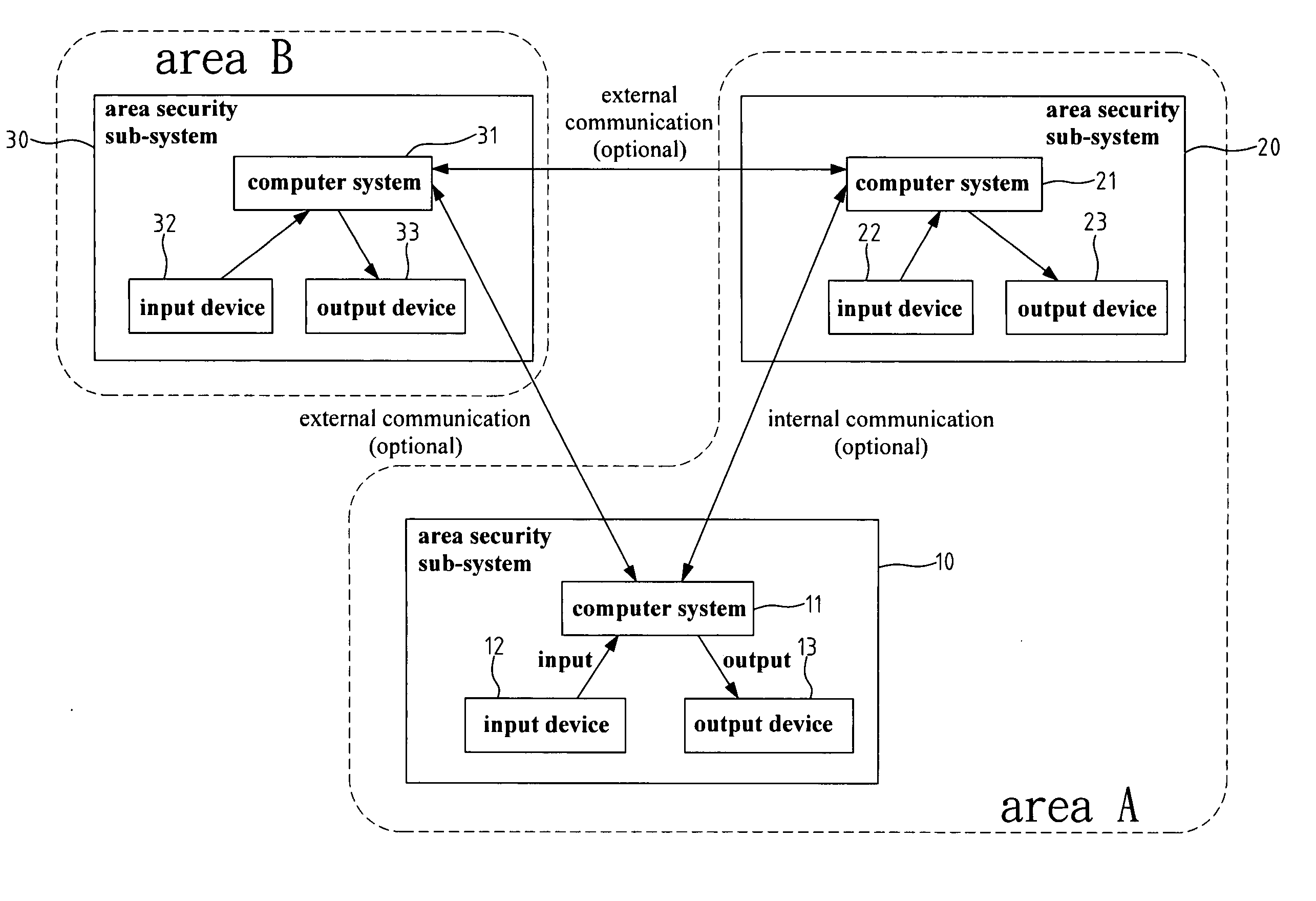
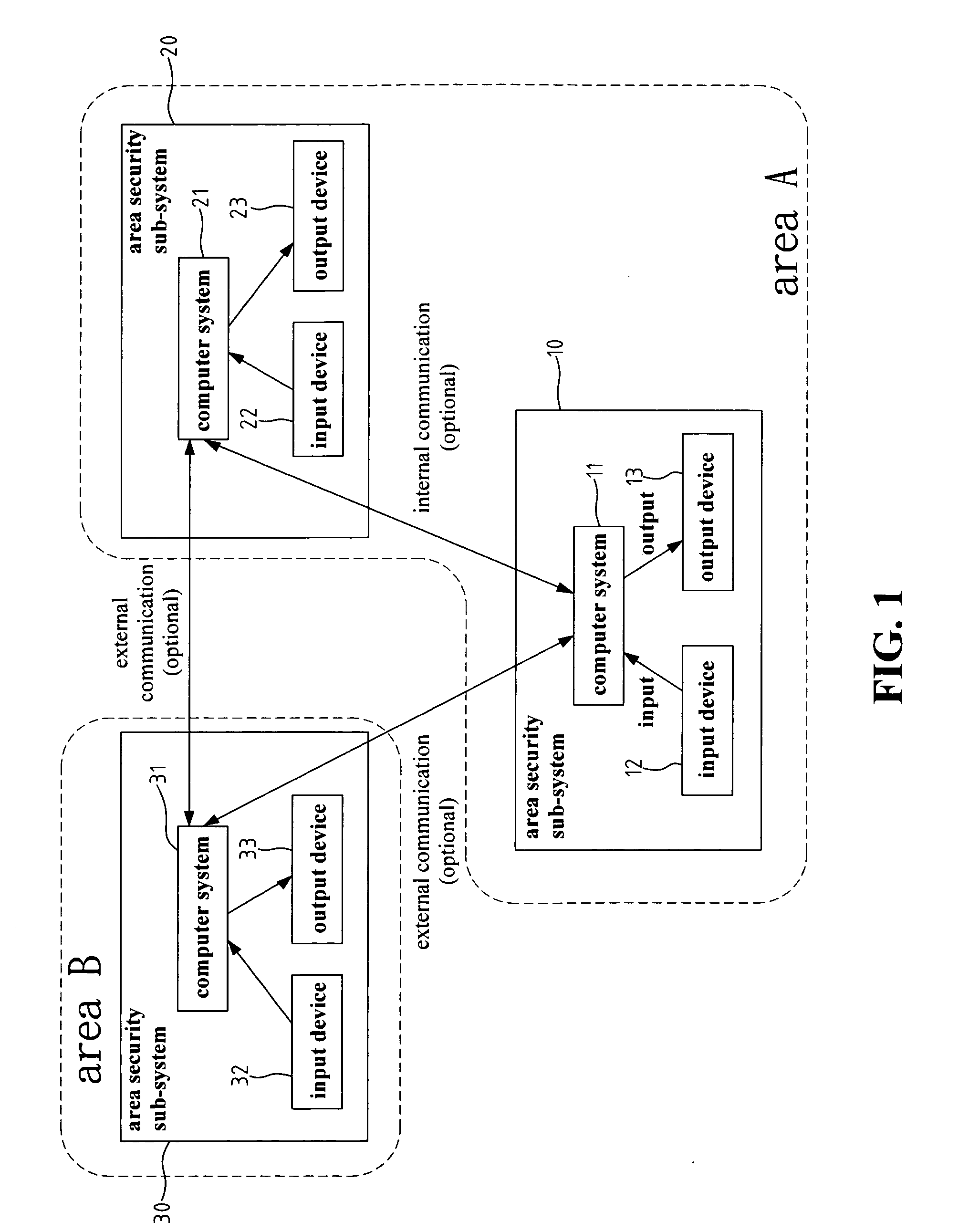
[0005] To overcome the aforementioned drawbacks for area security systems, the present invention provides an identification recognition system for area security. The identification recognition system for area security according to the present invention consists of a plurality of sub-systems for area security identification recognition. Each sub-system further includes independent computer systems as well as input / output (I / O) devices, and all sub-systems are connected with internal communication and video information system. To expand the security coverage and enhance the integral security efficiency, this area security system according to the present invention can also connect to external area security systems with real-time communication and real-time video information system.
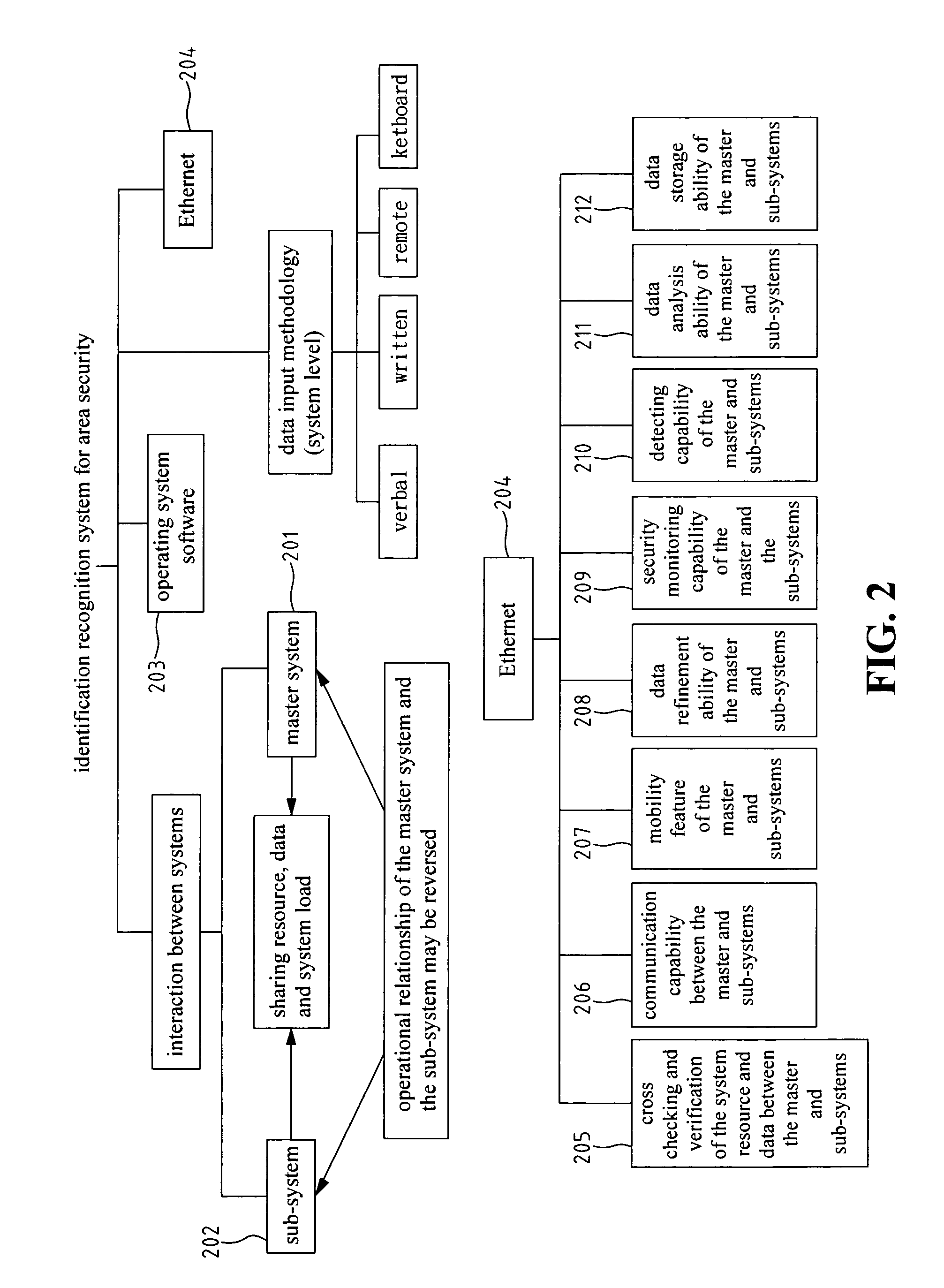
[0007] In addition to the quotient analysis module, the present invention also takes both advantages of mass storage and fast computation capacity of a computer system to iteratively verify the information of a target moving / living object against the saved standard reference information / pattern, and accomplishes fast and accurate identification recognition. The quotient analysis module of the present invention also performs behavior analysis and habit recognition for a target moving / living object to enhance the accuracy and sophistication of the identification recognition function. The result of the analysis as well as the episodic information is again saved back to the memory as the reference for the future identification recognition.
[0011] In order to minimize the accuracy deviation from the data collection, the preferred design according to the present invention includes one or more input devices arranged as an equilateral. For area geometry limitation, even a near equilateral arrangement of input devices helps.

Problems solved by technology

With conventional identification recognition techniques, the general limitation and drawbacks for an area security system include limited identification recognition ability, unreliable accuracy, and slowness in recognition speed, etc.
With such security loopholes, when there are multiple intruders invading multiple adjacent security areas simultaneously, it is hard for security management staff to perform in time efficient actions due to lacking of sufficient real-time global information regarding the whole security system.
Additionally, a conventional area security system also lacks of design for performing wired / wireless on-line communication with the other external / remote area security systems.
Since such local security system cannot stay in turn with security events / activities of any external / remote security systems, it is hard to perform proactive / preventive actions to the best of a security system in order to minimize any potential damage.
Similarly, any information regarding the security abnormality happened in a local security system cannot be broadcasted in time to the neighboring / remote security systems for helpful warning and preventive actions.
A conventional area security system also lacks of ability to save and utilize the information regarding the moving / living objects entering a security area.
Without a fast computation ability to perform real-time behavior analysis and habit recognition, a conventional security system also has limited ability and accuracy to perform the function of identification recognition.
Therefore, conventional area security systems have limited recognition functions, and easily misjudge an intruder or a non-intruder.
This may trigger a false alarm.

Method used


Image

  • Identification recognition system for area security
  • Identification recognition system for area security
  • Identification recognition system for area security

Examples


Embodiment Construction

[0018]FIG. 1 is a block diagram of an identification recognition system for area security according to the present invention. Depending on the covered area or the actual requirement, the identification recognition system may comprise more than one area security sub-systems. Without losing generality and for simple explanation, FIG. 1 illustrates with two internal area security sub-systems 10 and 20, and one external area security sub-system 30. Referring to FIG. 1, each area security sub-system 10 and 20 includes its own computer system 11 and 21, input devices 12 and 22, and output devices, 13 and 23, respectively. Each computer system includes at least one memory device and one operating system software. The two internal security sub-systems 10 and 20 belong to the same security area A. The security sub-system 30 belongs to another security area B.

[0019] In FIG. 1, the mutual communication between two internal area security sub-systems within the same security area (for example t...


PUM


Abstract

Disclosed is an identification recognition system for area security. The system consists of a plurality of area security sub-systems. Each sub-system includes an independent computer system as well as input / output devices, and all sub-systems are connected with internal audio and video communications. To expand the security coverage and enhance the integral security efficiency, this identification recognition system may also connect to external area security systems with real-time audio and video communications. With the saved information for the moving / living objects entering the security area as well as the fast computational ability, the identification recognition system for area security provides a real-time behavior analysis and habit recognition with high efficiency and accuracy of identification recognition.

Description

FIELD OF THE INVENTION [0001] The present invention generally relates to an identification recognition system, and more specifically to an identification recognition system for area security. BACKGROUND OF THE INVENTION [0002] The characteristic of a conventional technology for the area security identification recognition system is to perform security abnormality detection and identification recognition with respect to the specified security area. The logged information is only for the afterward inquiry and verification, and has never been used for real-time analysis, comparison and decision making for the occurrence of security conditions. With conventional identification recognition techniques, the general limitation and drawbacks for an area security system include limited identification recognition ability, unreliable accuracy, and slowness in recognition speed, etc. Other than this, with conventional technology, each area security system has limited coverage to its own local ar...

Claims


Application Information

Patent Timeline
IPC IPC(8): G08B19/00G06K9/00
CPCG06K9/00771G08B25/08G06K9/00973G06V10/94G06V20/52
Inventor HUANG, TSONGJYLIU, ITIE
Owner HUANG TSONGJY
Learn More