Planar Light Source Module for Fingerprint Recognition Apparatus

a fingerprint recognition and planar light source technology, applied in the field of planar light source modules for fingerprint recognition apparatuses, to achieve the effect of improving image sensing quality

Inactive Publication Date: 2007-07-05
NANOGATE OPTOELECTRONICS ROBOT
View PDF5 Cites 2 Cited by
  • Summary
  • Abstract
  • Description
  • Claims
  • Application Information

AI Technical Summary

Benefits of technology

[0005] Briefly, the object of the present invention is to provide a planar light source module for a fingerprint recognition apparatus to improve the image sensing quality.

Problems solved by technology

The scattered light emitted by the point light source or the line light source would cause non-uniformity and inconsistent directions, hence the sensed images would be blurred that further influences the recognition accuracy of the fingerprint recognition apparatus.

Method used


Image

  • Planar Light Source Module for Fingerprint Recognition Apparatus
  • Planar Light Source Module for Fingerprint Recognition Apparatus
  • Planar Light Source Module for Fingerprint Recognition Apparatus

Examples


Embodiment Construction

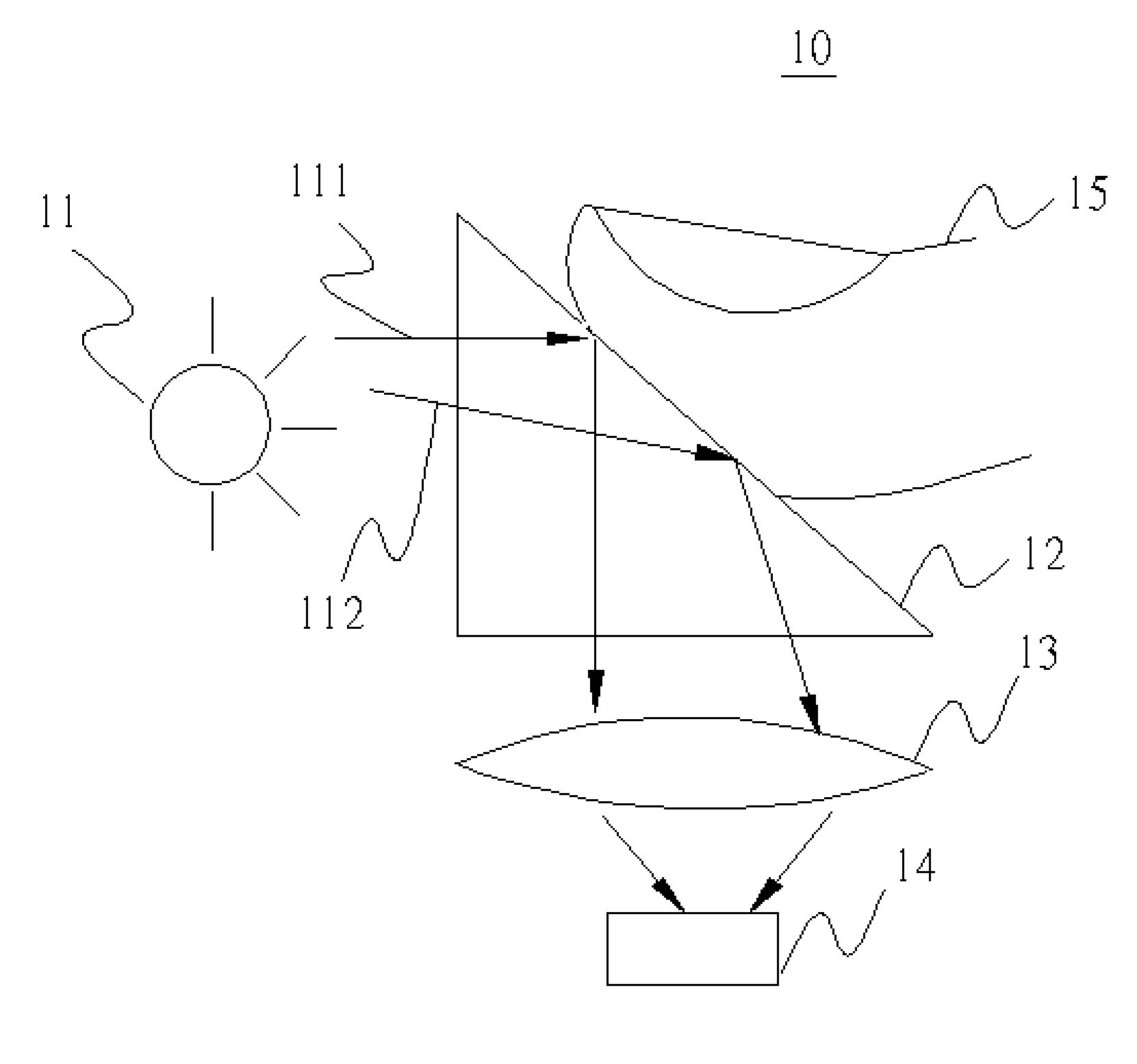
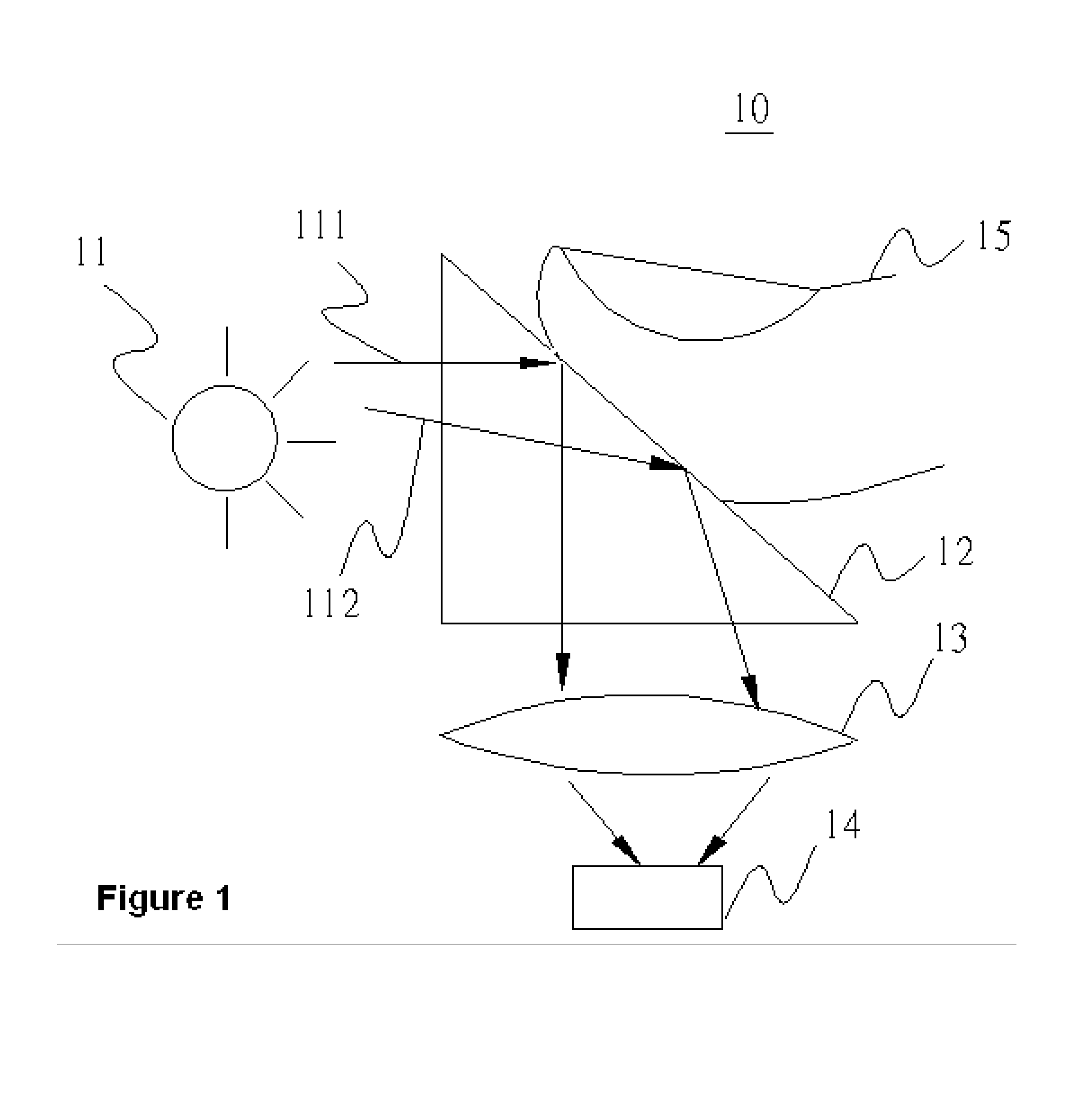
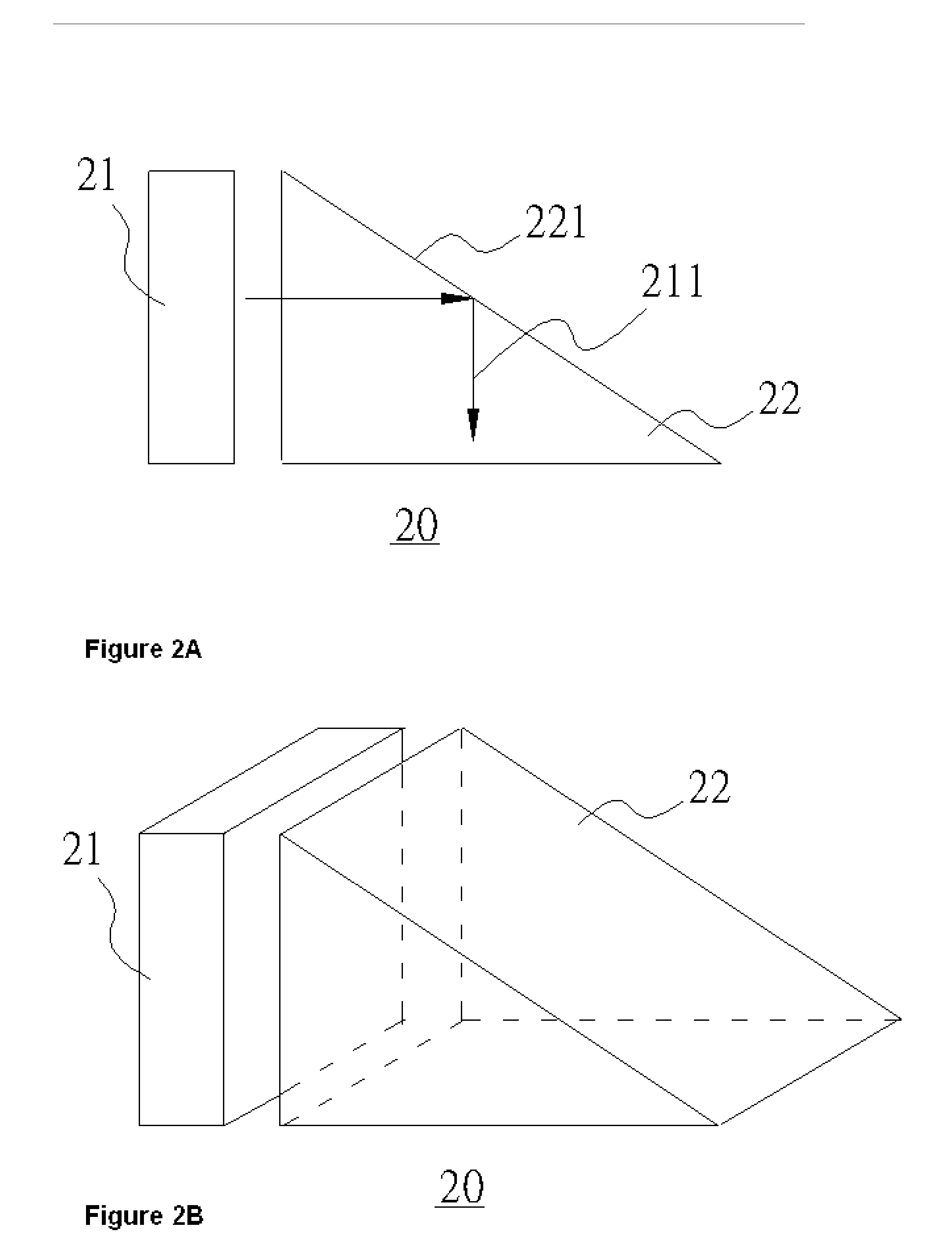
[0012] Referring to FIG. 2A, a schematic diagram illustrates a planar light source module for a fingerprint recognition apparatus according to an embodiment of the present invention. The planar light source module 20 comprises a planar light source 21 and an optical element 22. A planar incident light 211 is provided by the planar light source 21. The optical element 22 has a reflector 221. The planar incident light 211 is reflected by the reflector 221 to an optical sensing device of the fingerprint recognition apparatus (not shown in FIG. 2A). Referring to FIG. 2B, a perspective view illustrates the planar light source module 20 according to an embodiment of the present invention. In addition, the planar light source 21 can be adhered to the optical element 22 to achieve the better performance based on the demand. The planar light source 21 can be an electroluminescence plate (EL) or a backlight module. The optical element 22 is a prism and the reflector 221 is a bevel edge of the...


PUM


Abstract

A planar light source module for a fingerprint recognition apparatus is disclosed. A planar light source module comprises a planar light source and an optical element that includes a reflector. A planar incident light emitted by the planar light source can be reflected by the reflector of the optical element to an optical sensing device of the fingerprint recognition apparatus.

Description

FIELD OF THE INVENTION [0001] The present invention relates to a planar light source module for a fingerprint recognition apparatus and, more particularly, to integrate a planar light source and an optical element into a single element for the planar light source module. BACKGROUND OF THE INVENTION [0002] Currently, optical system often use a point light source or a line light source especially for the fingerprint recognition apparatus. The scattered light emitted by the point light source or the line light source would cause non-uniformity and inconsistent directions, hence the sensed images would be blurred that further influences the recognition accuracy of the fingerprint recognition apparatus. [0003] Referring to FIG. 1, a schematic diagram illustrates a conventional fingerprint recognition apparatus architecture. The fingerprint recognition apparatus 10 comprises a point light source 11, a prism 12, a convex lens 13 and an image sensing device 14. An image of a fingerprint fro...

Claims


Application Information

Patent Timeline
Patent Type & Authority Applications(United States)
IPC IPC(8): G03H1/00
CPCG06K9/00046G06V40/1324
Inventor KUO, PENG-CHIA
Owner NANOGATE OPTOELECTRONICS ROBOT
Why Eureka
Try Eureka