Backlight unit and liquid crystal display device having the same

Active Publication Date: 2007-07-05
SHARP KK
View PDF19 Cites 122 Cited by
  • Summary
  • Abstract
  • Description
  • Claims
  • Application Information

AI Technical Summary

Benefits of technology

[0010] In order to overcome the problems described above, preferred embodiments of the present invention provide a

Problems solved by technology

Although the cold-cathode tube is mainly used for a liquid crystal having a larger screen size than a cellular telephone and a PDA, environmental issues are increasingly important in recent years, and it is considered to be undesirable to use a cold-cathode tube using mercury.
However, the liquid crystal display device including this backlight unit has a problem that the colors of individual LEDs can be visually recognized in the area corresponding to the vicinity of the incide

Method used


Image

  • Backlight unit and liquid crystal display device having the same
  • Backlight unit and liquid crystal display device having the same
  • Backlight unit and liquid crystal display device having the same

Examples


first preferred embodiment

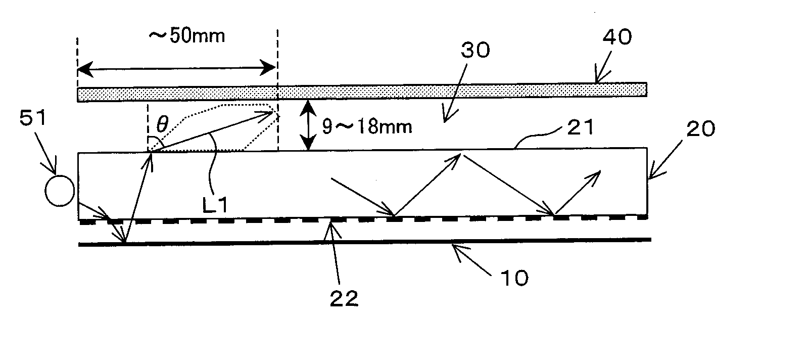
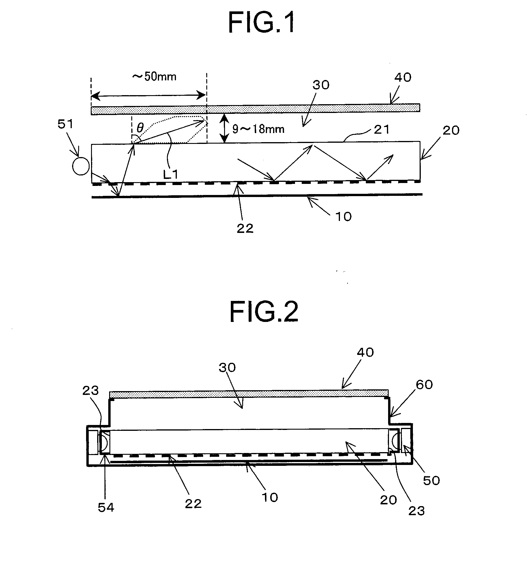
[0092] A backlight unit and a liquid crystal display device including the same according to a first preferred embodiment of the present invention will be described with reference to FIGS. 1 to 37. FIG. 1 shows a cross section depicting the principle of the backlight unit according to the first preferred embodiment. As shown in FIG. 1, the backlight unit that is an area light source has an area light guide plate (the light guide section) 20 preferably having a substantially rectangular plane shape, for example. In the vicinity of at least one side end surface of the light guide plate 20, a light source (a discrete light source section) 51 is disposed. For example, the light source 51 is configured of a plurality of LEDs having light emission wavelengths of different spectra. Alternatively, the light source 51 is configured of a plurality of LEDs having different light emission quantities. In the drawing, above a light emission plane 21 of the light guide plate 20, optical sheets such...

example 8

[0104]FIG. 9 shows the configuration of a backlight unit according to example 8. As shown in FIG. 9, near incident planes 23 of a light guide plate 20, a plurality of red LEDs 50 (R), green LEDs 50 (G), and blue LEDs 50 (B) are substantially evenly arranged. The number of the LEDs 50 in individual colors is decided in consideration of the input electric power for the LEDs in each color and the illumination color of a target backlight unit. Generally, the number of the LEDs50 (G) is the greatest. The LEDs 50 are arranged at even intervals, whereby the distances from the incident plane 23 at which the colors of the individual LEDs 50 are visually recognized are almost similar for any of the LEDs 50. Accordingly, the thickness of the air space 30 which is arranged not to visually recognize color irregularities can be established at the minimum. In addition, since color irregularities are more physiologically visually recognizable than luminance variations, this is an effective scheme i...

example 9

[0105]FIGS. 10A to 10C show the configuration of a backlight unit according to example 9. FIG. 10A shows the configuration when an LED circuit board 56 of the backlight unit is seen in parallel with the substrate plane, and FIG. 10B shows the configuration when the LED circuit board 56 is seen vertically to the substrate plane. FIG. 10C shows the cross sectional configuration of the backlight unit. As shown in FIGS. 10A to 10C, a plurality of LEDs 50 are linearly arranged along the longitudinal direction of the LED circuit board 56. The plurality of the LEDs 50 are arranged along the longitudinal direction of the incident plane of a light guide plate 20. The red, green, and blue LEDs 50 are arranged substantially evenly. Moreover, the LEDs 50 are mounted at the position (the lower end side in the drawing) on one side in the short direction of the LED circuit board 56. The LED circuit board 56 is incorporated in the backlight unit on the lower end side in the drawing as the LEDs 50 a...


PUM


Abstract

A backlight unit has a light source, a reflection sheet, a light guide plate, an air space, and a diffuser, wherein the reflection sheet, the light guide plate, the air space, and the diffuser are overlaid in this order. The light source is configured to arrange individual light sources having different spectra or different light emission quantities near an incident plane of the light guide plate, and on a plane facing the reflection sheet of the light guide plate, scatter dots are disposed which take light propagating through the light guide plate out of the reflection sheet side. The backlight unit and a liquid crystal display device including the same have excellent display quality.

Description

BACKGROUND OF THE INVENTION [0001] 1. Field of the Invention [0002] The present invention relates to a backlight unit and a liquid crystal display device including the same. [0003] 2. Description of the Related Art [0004]FIG. 70 shows the schematic structure of a conventional liquid crystal display device. The liquid crystal display device has a liquid crystal display panel 110 and a backlight unit. The backlight unit is provided with a light guide plate 114 and cold-cathode tubes 116 disposed at two end surfaces opposite to each other of the light guide plate 114. Around the cold-cathode tubes 116, reflectors 117 are disposed which efficiently transmit light into the light guide plate 114. Lens sheets 111 and 112 and a diffuser sheet 113 are disposed between the liquid crystal display panel 110 and the backlight unit. In addition, a reflection sheet 115 is disposed on the back side of the light guide plate 114. [0005] For the backlight unit used in the liquid crystal display device...

Claims


Application Information

Patent Timeline
IPC IPC(8): F21V7/04F21S8/04F21V8/00G02B6/00
CPCG02B6/003G02B6/0036G02F2001/133628G02B6/0085G02F1/133615G02B6/0046G02F1/133628F21S8/04
Inventor HAMADA, TETSUYASUZUKI, TOSHIHIROISHIWA, MASARU
Owner SHARP KK
Why Eureka
Try Eureka