Enhanced block-based motion estimation algorithms for video compression

a motion estimation and block-based technology, applied in the field of digital signal compression, coding and representation methods and systems, can solve the problems of consuming huge computation power in the video encoder, and a large number of peopl

Inactive Publication Date: 2007-07-05
THE HONG KONG UNIV OF SCI & TECH
View PDF4 Cites 92 Cited by
  • Summary
  • Abstract
  • Description
  • Claims
  • Application Information

AI Technical Summary

Benefits of technology

[0024] One advantage of certain embodiments of the second aspect of the invention is that the motion vectors they produce can be encoded in the same format code as in conventional algorithms, except that the conventional codes for the location values should respectively be interpreted as the possible locati

Problems solved by technology

This is a huge number that can consume huge computation power in a video encoder.
A separate but important issue in defining current video coding standards, is the use of subpixel motion vectors in

Method used


Image

  • Enhanced block-based motion estimation algorithms for video compression
  • Enhanced block-based motion estimation algorithms for video compression
  • Enhanced block-based motion estimation algorithms for video compression

Examples


first embodiment

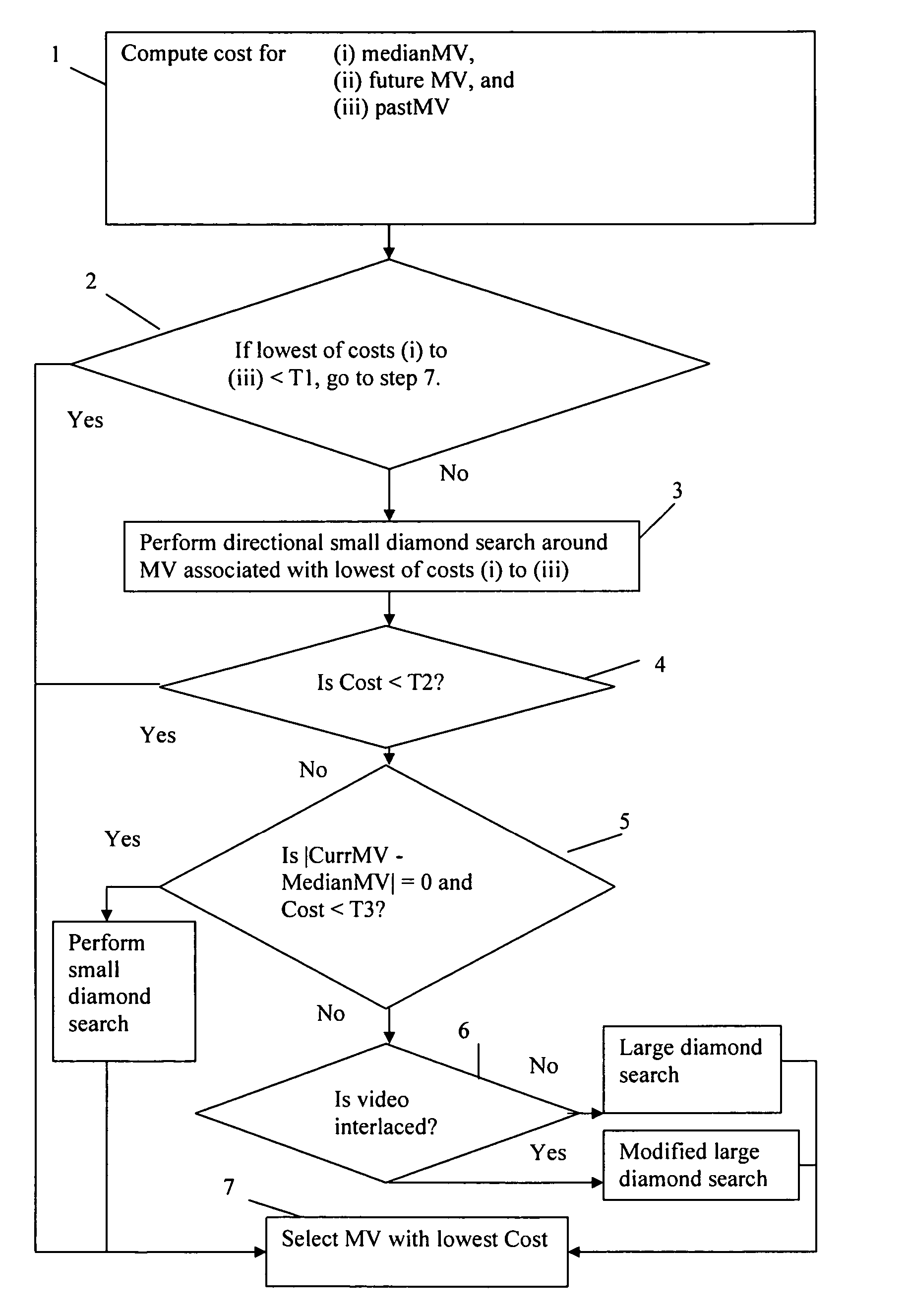
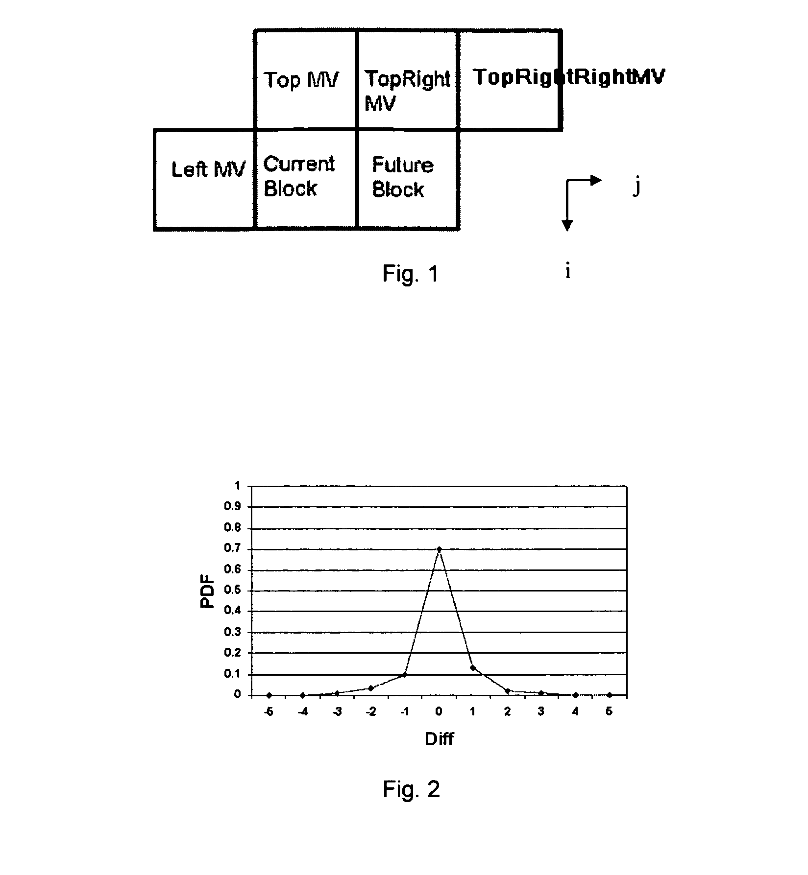
[0035] the invention employs many features of the PMVFAST algorithm, but improves upon PMVFAST (and other existing algorithms) by considering a few neighboring blocks instead of just one block. Eqn. (2) and (3) show that the choice of the MV of the current block directly affects the RD cost of the neighboring blocks, including the right block (or the (i, j+1)th block), the lower-left block (or the (i+1, j−1)th block), and the lower block (or the (i+1, j)th block). This is because the current MV would affect the predicted MV of these neighboring blocks and thus in turn affect the optimal motion vectors for those blocks. These are “future” blocks as motion estimation has not been performed on them when the current block is processed. We cannot compute the optimal motion vector of these future blocks concurrently with the current block because this we would require computing the optimal motion vectors for all the blocks in the whole frame simultaneously as in Eqn. (2), which would incu...

second embodiment

[0076] We now turn to the invention, which illustrates the second aspect of the invention.

[0077] As described above, conventional full integer pixel allows motion vectors to take on location values in each direction of −2.0, −1.0, 0, 1.0, 2.0, etc. In the second embodiment of the invention, the possible location values are selected to be close to the predictor. For the location value which is nearest to 0, we can use (instead of 1.0) another location value such as 0.85 such that the allowable location values would include −2.0, −0.85, 0, 0.85, 2.0, etc. The advantage of this is that statistically motion vectors tend to be close to 0. And thus by choosing the location closer to 0, we would be closer to the true motion vector and thus can give better motion compensation that can lead to higher compression efficiency. Similarly, the other location values can be changed. As an example, the location value of 2.0 can be changed to 1.9 such that the allowable location values would include ...


PUM


Abstract

Method, systems and software are proposed for obtaining for blocks of a first image similar blocks of a second image (the “reference image”). The blocks of the first image are processed sequentially, for each block trying out a number of candidate locations in the second image and evaluating a cost function for each. Each candidate location in the second image is displaced by a respective motion vector from the block of the first image. In a first aspect of the invention the cost function is a function of a predicted motion vector for future blocks of the first image (i.e. blocks of the first image which have not yet been processed). In a second aspect of the invention the motion vectors are given by location values which are not all whole pixel spacings, halves of the pixel spacing, or quarters of the pixel spacing.

Description

RELATED APPLICATION [0001] The present application claims priority to U.S. provisional patent application 60 / 691,181, filed Jun. 17, 2005, the entire disclosure of which is incorporated herein by reference.FIELD OF THE INVENTION [0002] The present invention relates generally to methods and systems for digital signal compression, coding and representation, and more particularly to methods and systems using multi-frame motion estimation (ME). It further relates to a computer program product, such as a recording medium, carrying program instructions readable by a computing device to cause the computing device to carry out a method according to the invention. BACKGROUND [0003] Due to the huge size of the raw digital video data (or image sequences) used by present day multimedia applications, compression must be applied to such data so that it can be transmitted and stored. There have been many important video compression standards, including the ISO / IEC MPEG-1, MPEG-2, MPEG-4 standards ...

Claims


Application Information

Patent Timeline
IPC IPC(8): G06K9/36G06K9/46
CPCH04N19/56H04N19/52H04N19/57H04N19/523H04N19/533
Inventor AU, OSCAR CHI LIMWONG, HOI MING
Owner THE HONG KONG UNIV OF SCI & TECH
Why Eureka
Try Eureka