Assistant for implant stent
- Summary
- Abstract
- Description
- Claims
- Application Information
AI Technical Summary
Benefits of technology
Problems solved by technology
Method used
Image

Examples
first embodiment
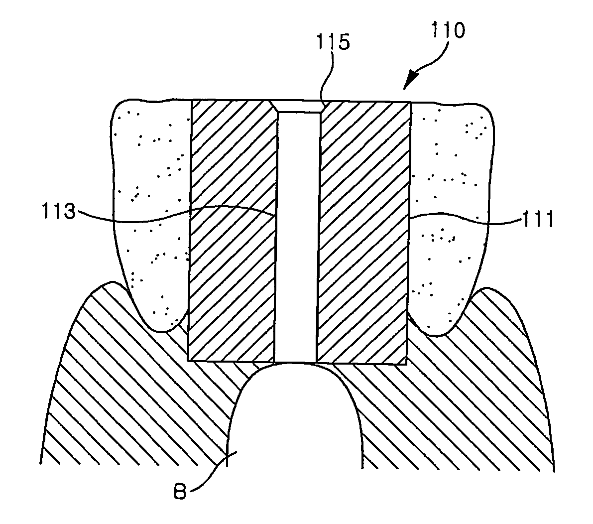
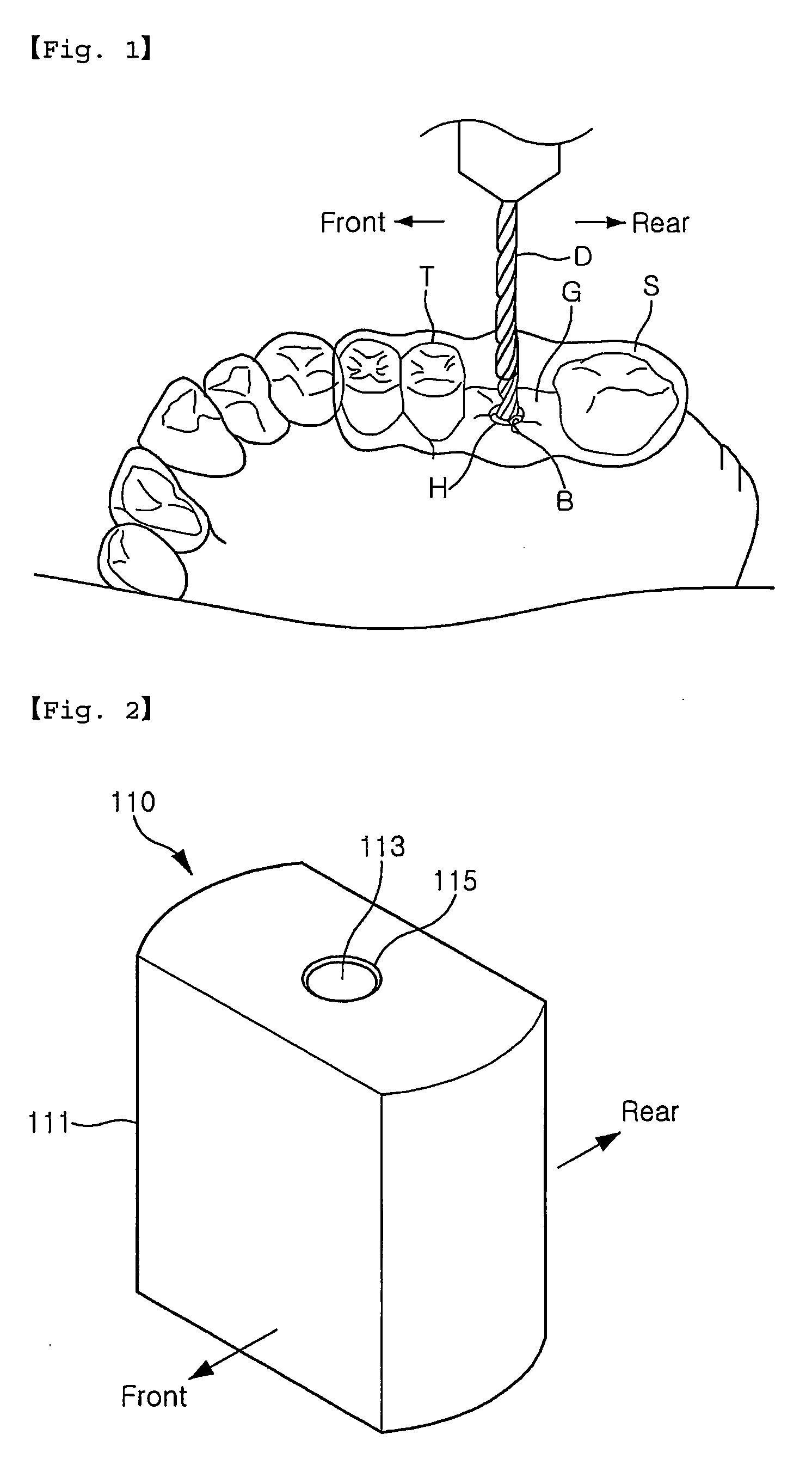
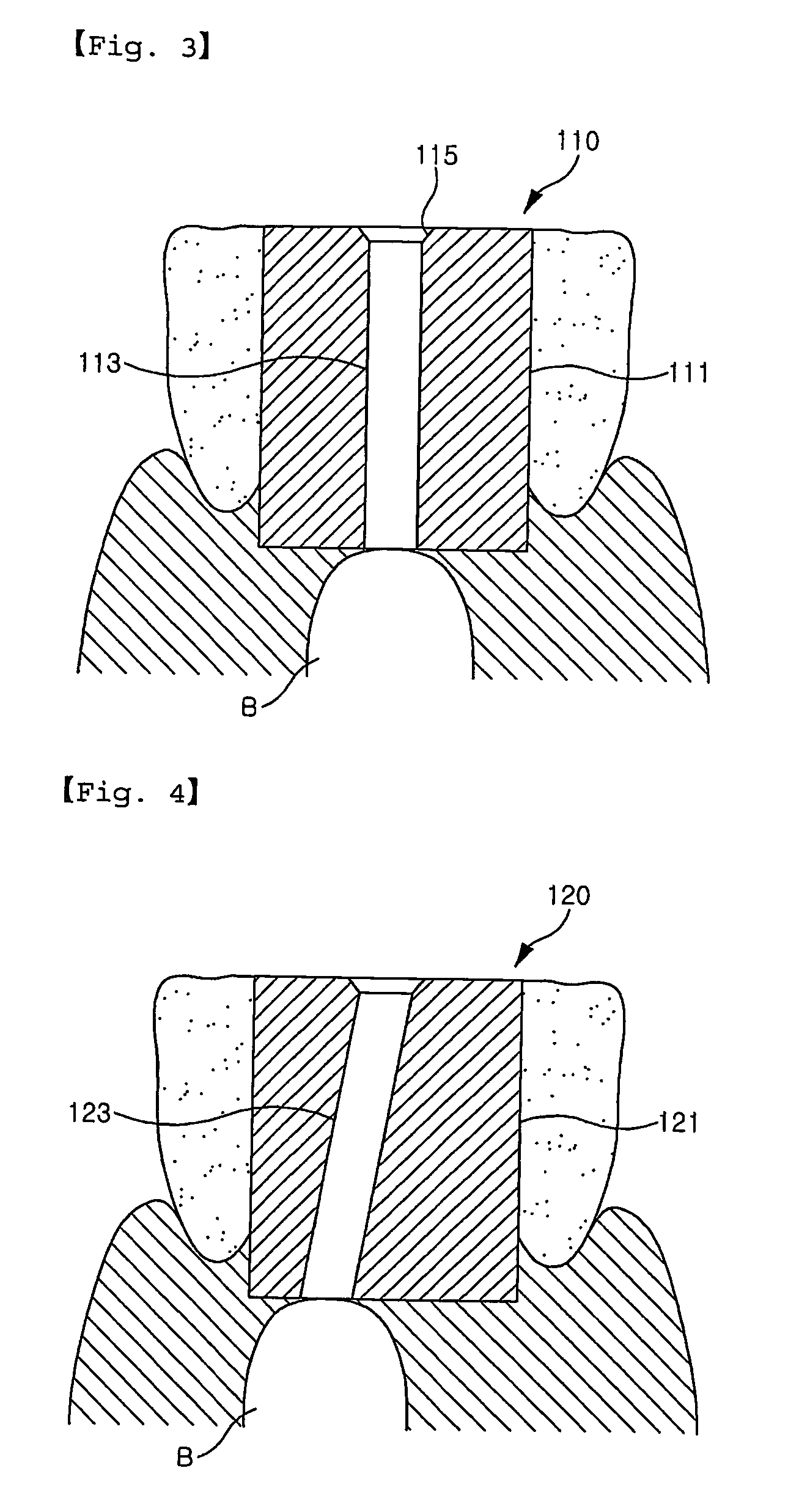
[0073] As illustrated in FIGS. 2 and 3, an assistant for implant stent 110 comprises a body 111 of which horizontal section is rectangular with opposite rounded sides (i.e., sides formed in a direction perpendicular to the fore and aft direction shown in the figures) and has a predetermined vertical length, and a drill insertion hole 113 which is bored through the body 111. At this time, the drill insertion hole 113 is formed to pass through the body 111 vertically from the top to the bottom of the body. Further, an upper opening 115 corresponding to an inlet of the drill insertion hole 113 is formed to be narrowed downward such that a drilling means for drilling an alveolar bone B can be easily inserted into the drill insertion hole. Here, although the body 111 of the assistant for implant stent 110 is shaped to be rectangular with the opposite rounded side, the present invention is not limited thereto. The body may be shaped to be circular, elliptical or rectangular with rounded c...
second embodiment
[0084] Referring to the second embodiment illustrated in FIGS. 8 and 9, an assistant for implant stent 210 comprises a body 211 which includes a body portion 211a with a predetermined vertical length and a support portion 211b formed on a top surface of the body portion 211a to have a sectional area greater than the body portion 211a and a predetermined thickness, and a drill insertion hole 215 which is bored from a top surface of the body 211, i.e. a top surface of the support 211b, to a bottom surface of the body 211. Here, a cross section of the body 211 is rectangular with opposite rounded sides but is not limited thereto.
[0085] At this time, the drill insertion hole 215 is bored vertically through the body 211 from the top surface of the support body 211b to the bottom surface of the body 211. Further, an upper opening 217 is formed to be narrowed downward such that a drilling means for drilling an alveolar bone B can be easily inserted into the drill insertion hole.
[0086] Fur...
third embodiment
[0097] As illustrated in FIGS. 15 to 17, an assistant for implant stent 310 comprises a body 311 which includes a body portion 311a with a predetermined vertical length and a support portion 311b protruding by a predetermined length in the fore and aft direction and formed on a bottom surface of the body portion 311a to have a predetermined thickness, and a drill insertion hole 315 which is bored from a top surface of the body portion 311a to the bottom surface of the support portion 311b. Here, a cross section of the body 311 is rectangular with opposite rounded sides perpendicular to the fore and aft direction but is not limited thereto.
[0098] At this time, the drill insertion hole 315 is bored vertically from the center of the top surface of the body 311 to the bottom surface of the body 311, i.e. the bottom surface of the support portion 311b. Further, an upper opening 317 is formed to be narrowed downward such that a drill for drilling an alveolar bone B can be easily inserted ...
PUM
 Abstract
Description
Claims
Application Information
 - R&D
- Intellectual Property
- Life Sciences
- Materials
- Tech Scout
- Unparalleled Data Quality
- Higher Quality Content
- 60% Fewer Hallucinations
Browse by: Latest US Patents, China's latest patents, Technical Efficacy Thesaurus, Application Domain, Technology Topic, Popular Technical Reports.
© 2025 PatSnap. All rights reserved.Legal|Privacy policy|Modern Slavery Act Transparency Statement|Sitemap|About US| Contact US: help@patsnap.com