
Cervimetry control apparatus

a control apparatus and cervical technology, applied in the field of obstetric devices, can solve the problems of subjective accuracy of such a measurement, and achieve the effect of accurate and precise measurement of cervical dilation

Inactive Publication Date: 2007-07-05
INTRAPARTUM VENTURES
View PDF79 Cites 36 Cited by
  • Summary
  • Abstract
  • Description
  • Claims
  • Application Information

AI Technical Summary

Benefits of technology

[0007]The present invention advantageously provides a method and system for the accurate and precise measuring of cervical dilation during labor, as well as a method and system for performing cervical dilation. The medical device of the present invention may include an elongate body defining a proximal end and a distal end, with the elongate body further including an inflation lumen. An expandable element may be coupled to the elongate body in fluid communication with the inflation lumen, and an array of movable elements may be circumferentially disposed about the elongate body, with the array of movable elements being movably coupled to the elongate body by a plurality of wires. The medical device may also include a measurement mechanism able to determine a radial spacing of the array of movable elements, where the measurement mechanism can include a tension ring coupled to the plurality of wires. In addition, a dilation indicator can be provided in communication with the measurement mechanism, while at least one pressure sensor may be coupled to at least one of the array of movable elements. Moreover, a distal pressure sensor can be coupled to the distal end of the elongate body, with the medical device also providing a control element in communication with the at least one pressure sensor and the distal pressure sensor. The medical device can also include an inflation source in fluid communication with the expandable element, as well as an exhaust valve in fluid communication with the expandable element. Furthermore, the medical device may include a camera as well as a lighting element coupled to the distal end of the elongate body, thereby providing visual feedback to aid in the positioning of the device.
[0008]The control element of the present invention may further provide for monitoring and controlling the operation of the medical device. The control element may be in communication with the one or more sensors disposed on the medical device, as well as being in communication for control and / or monitoring of the additional components of the medical device, such the camera, lighting source, inflation source, or the like. The control element may provide a display or other indication elements for conveying information, such as pressure, size, etc. to a physician during a particular procedure. Moreover, the control element may provide for additional patient safety by having an automatic alarm and / or shut down process in response to measurements and / or conditions that differ from a pre-determined set of parameters.

Problems solved by technology

While an obstetrician may be fairly experienced in performing a manual cervical diameter measurement, the accuracy of such a measurement can be highly subjective and can further vary depending on the particular experience, judgment, and even finger size of the attending physician.

Method used


Image

  • Cervimetry control apparatus
  • Cervimetry control apparatus
  • Cervimetry control apparatus

Examples


Embodiment Construction

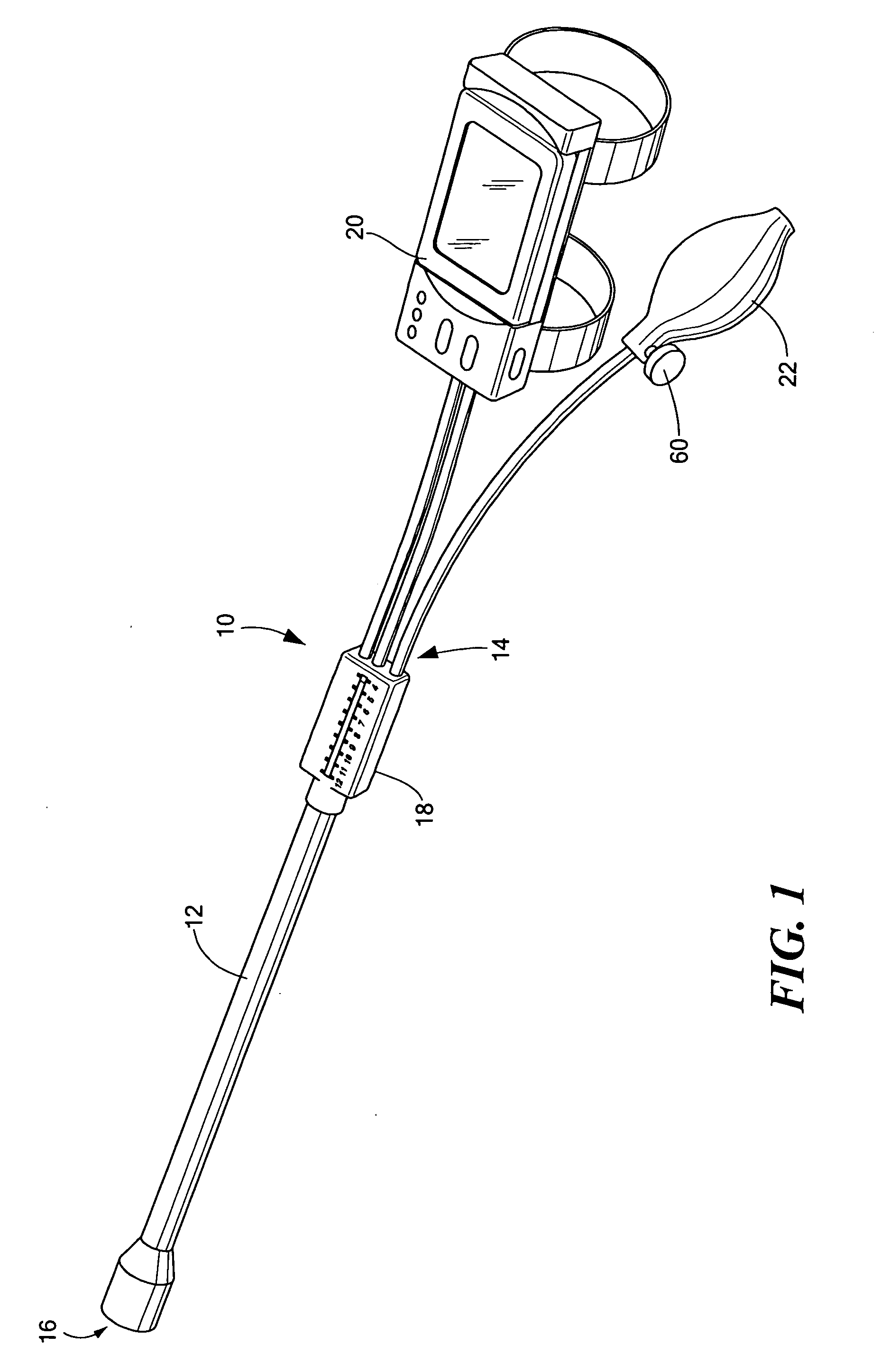
[0029]As shown in FIG. 1, the present invention provides a medical device 10 for measuring and performing cervical dilation. The medical device 10 includes an elongate body 12 defining a proximal end 14 and a distal end 16. The medical device 10 may further include a dilation indicator 18 coupled to the proximal end 14 of the elongate body 12 that is capable of providing a visual indicator of the dilation measurement made by the medical device 10, as well as a control element 20 and an inflation source 22, which will be discussed in more detail below.

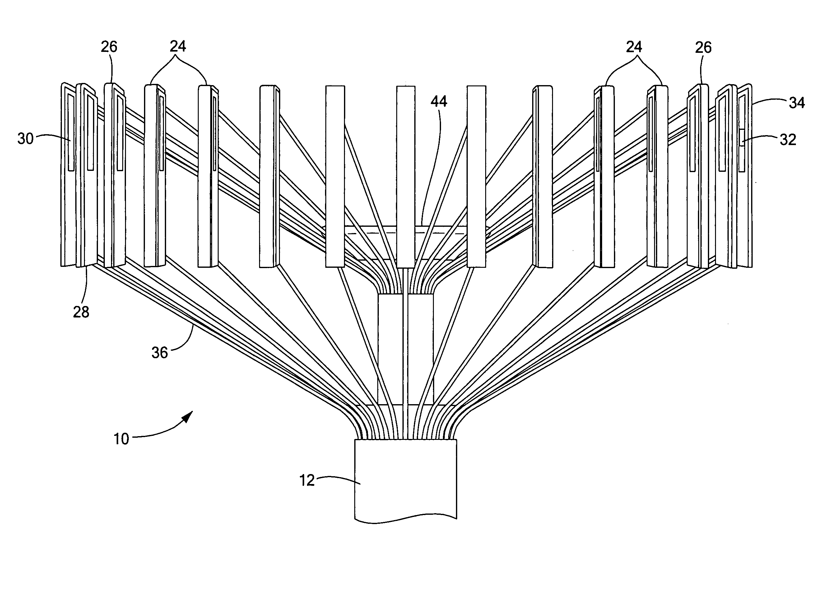
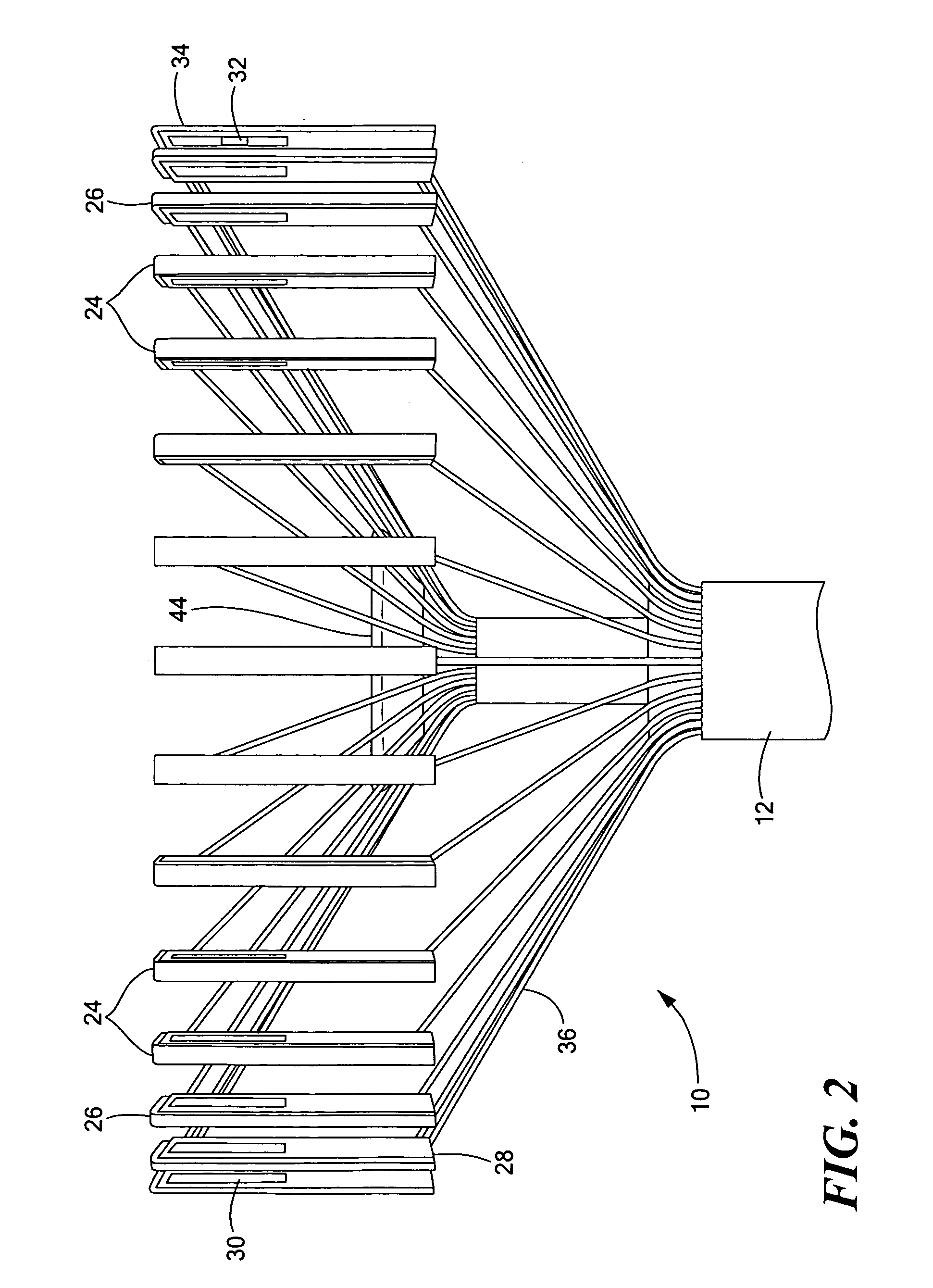
[0030]Now referring to FIG. 2, the medical device 10 may further include an array of movable elements 24 disposed circumferentially about an axis of the elongate body 12, where the array of movable elements 24 is located in proximity to the distal end 16 of the elongate body 12. The array of movable elements 24 are movable in a radial direction as to expand and contact with the tissue of the cervix when positioned for measurement of cer...


PUM


Abstract

The present invention provides a medical device for measuring cervical dilation including an elongate body defining a proximal end and a distal end, as well as an expandable element coupled to the distal end of the elongate body. An array of movable elements may be disposed circumferentially about the elongate body, where the array of movable elements is movably coupled to the distal end of the elongate body by a plurality of wires. The medical device may further include a measurement mechanism able to determine a radial spacing of the array of movable elements, as well as a dilation indicator in communication with the measurement mechanism. One or more pressure sensors may be coupled to the array of movable elements, whereby a control element is in communication with the pressure sensors. In addition, an inflation source may be included in fluid communication with the expandable element.

Description

CROSS-REFERENCE TO RELATED APPLICATION[0001]This application is a continuation-in-part of and claims priority to both pending Utility patent application Ser. No. 11 / 401,623, filed Apr. 10, 2006, entitled METHOD FOR CERVICAL DILATION AND / OR MEASUREMENT, and pending Utility patent application Ser. No. 11 / 401,749, filed Apr. 11, 2006, entitled CERVICAL DILATION MEASUREMENT APPARATUS, each of which is a continuation-in-part of and claims priority to pending Utility patent application Ser. No. 11 / 321,061, filed Dec. 29, 2005, entitled CERVIMETER, the entirety of each of which is incorporated herein by reference.STATEMENT REGARDING FEDERALLY SPONSORED RESEARCH OR DEVELOPMENT[0002]n / aFIELD OF THE INVENTION[0003]The present invention relates to obstetric devices and more particularly, to a method and apparatus for monitoring and controlling cervical dilation.BACKGROUND OF THE INVENTION[0004]During the later stages of pregnancy, the cervix typically undergoes numerous physical changes which ...

Claims


Application Information

Patent Timeline
Patent Type & Authority Applications(United States)
IPC IPC(8): A61B5/103A61B5/117
CPCA61B5/1076A61B5/435A61B2562/247A61B2562/0247A61B2562/043A61B5/6885
Inventor DUBEY, DHARMESHBAIRD, TIM
Owner INTRAPARTUM VENTURES
Learn More