Wireless pressure sensor

a technology of fluid pressure sensor and wired connection, which is applied in the direction of fluid pressure measurement, measurement devices, instruments, etc., can solve the problems of increasing the cost of manufacturing the sensor, preventing the accuracy of any direct absolute pressure measurement, and either the reference environment does not allow simple, direct measurement of both absolute and gauge pressure. , to achieve the effect of improving the performance of the pressure sensor

Inactive Publication Date: 2007-07-12
MFR & TRADERS TRUST COMPANY M&T
View PDF4 Cites 14 Cited by
  • Summary
  • Abstract
  • Description
  • Claims
  • Application Information

AI Technical Summary

Benefits of technology

[0010] Also described is a method of improving the performance of a pressure sensor by opening a fluid passageway between the interior of a housing of the pressure sensor and the outside of said housing and closing the passageway prior to measuring a fluid pressure.

Problems solved by technology

Sealing the sensor package in a vacuum increases the cost of manufacturing the sensor, while sealing the package at the factory ambient pressure prevents the accuracy of any direct absolute pressure measurement since moving the sensor to a different altitude will cause a pressure differential between the reference pressure of the sensor and the ambient air pressure.
Either reference environment does not allow simple, direct measurement of both absolute and gauge pressure.

Method used


Image

  • Wireless pressure sensor
  • Wireless pressure sensor
  • Wireless pressure sensor

Examples


Embodiment Construction

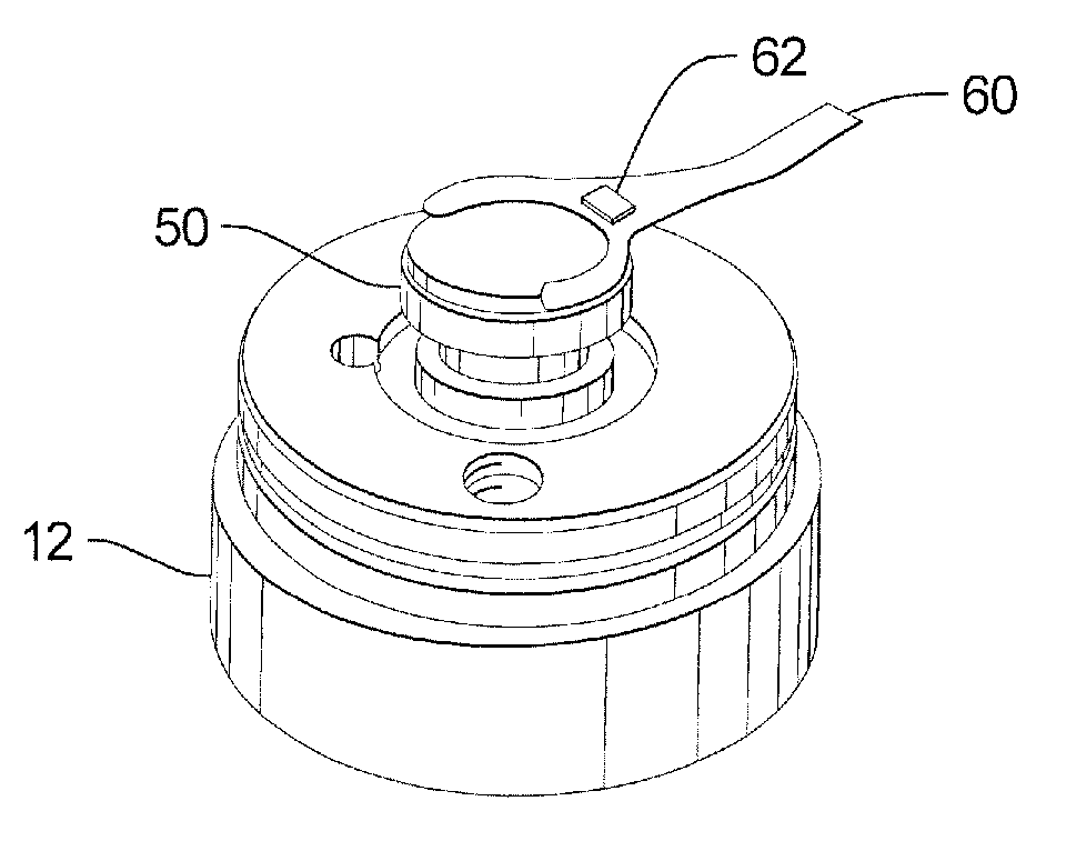
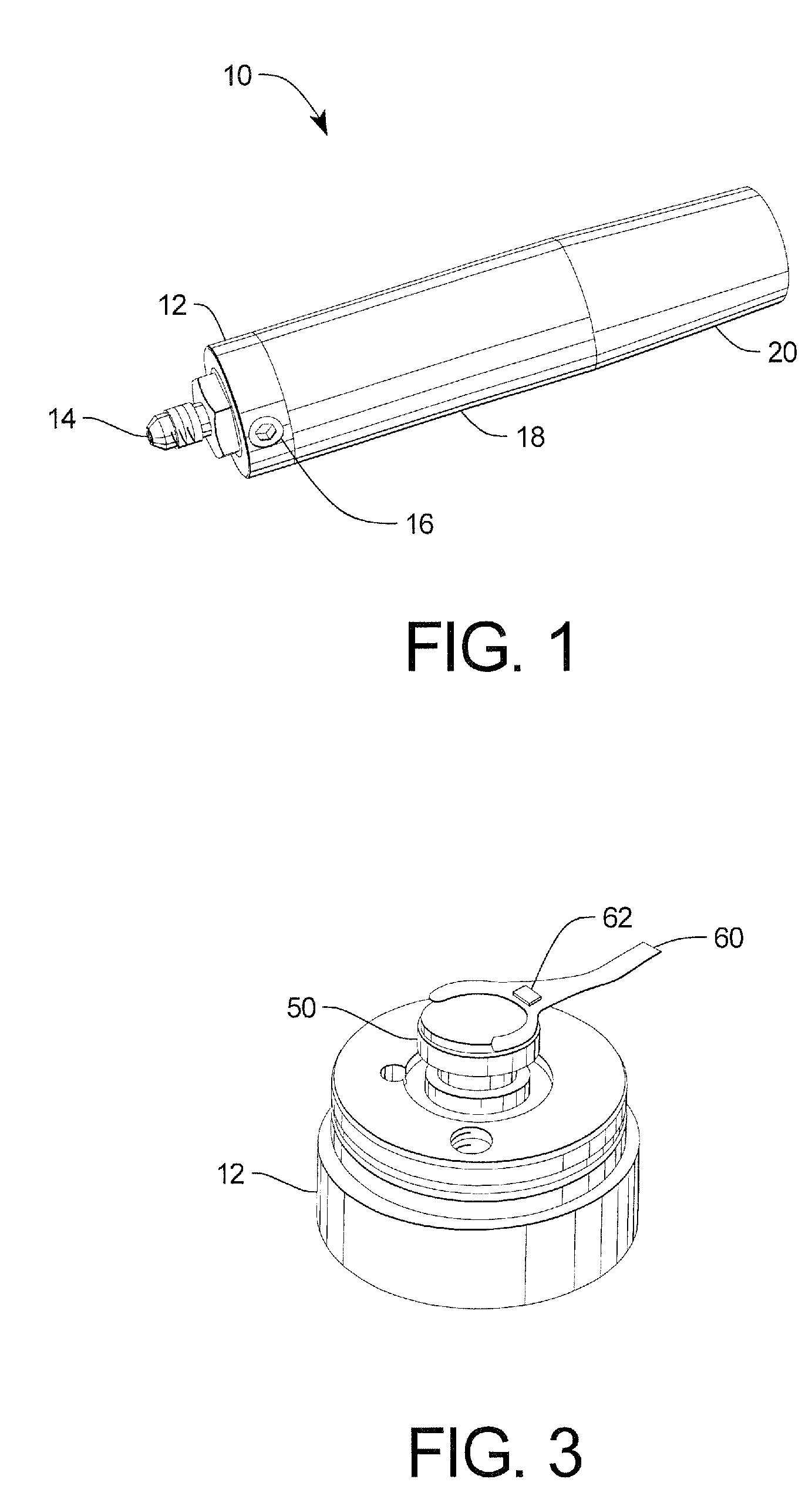
[0020] Turning now to the drawings FIG. 1 shows a perspective view of a wireless pressure sensor 10 in accordance with one embodiment of the present invention. The sensor 10 has a pressure cap 12 with a pressure port 14 for receiving a fluid, a pressure equalizing or reference port 16 in the pressure cap 12, a sleeve-like enclosure or body 18, and an antenna 20.

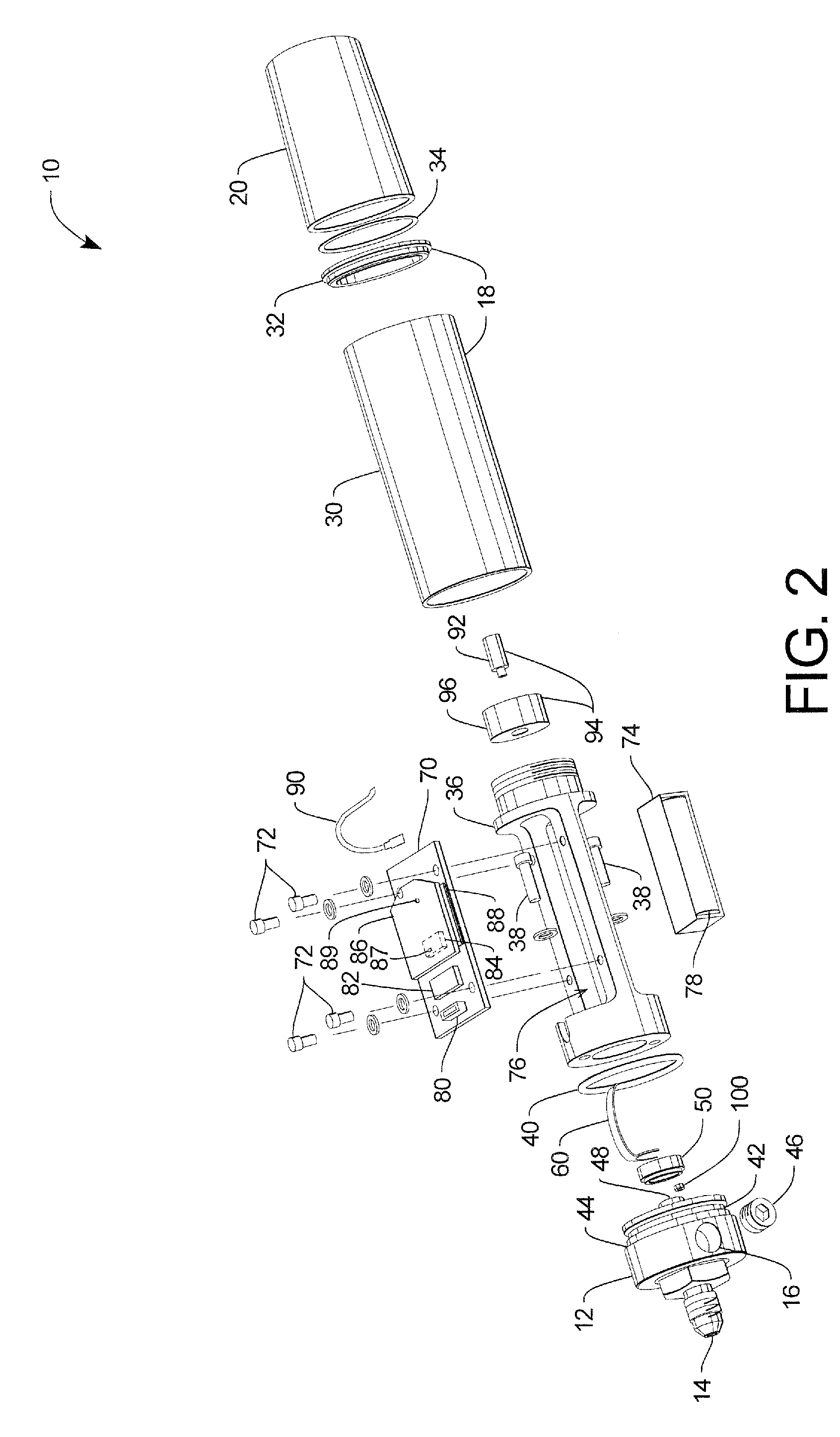
[0021]FIG. 2 is an exploded view of the sensor 10 showing various components of the sensor 10. The body 18 is manufactured from two parts, a case 30 and an end cap 32 which is press fit into the case 30 to provide a flat surface for an O-ring 34 located between the body 18 and the antenna 20. Female threads in the antenna 20, manufactured by Antennex of Glaendale Heights, Ill., mate with male threads formed on a high tension aluminum frame 36. The high tension aluminum frame 36 provides a rigid structure for the pressure gauge 10. The frame 36 is fastened to the pressure cap 12 by screws 38. A second O-ring 40 fits into a gr...


PUM

PropertyMeasurementUnit
temperatureaaaaaaaaaa

Abstract

A battery powered wireless fluid pressure sensor has a sealed chamber which can be vented to the outside atmosphere through a re-sealable reference port to allow a user to set the reference atmosphere inside the pressure sensor enabling the pressure sensor to provide absolute, gauge and true gauge pressure readings. The sensor calculates and transmits the fluid pressure taking into account the temperature of the pressure transducer, the temperature of the electronic devices and the barometric pressure inside the sealed chamber to provide accurate pressure measurements over a wide range of operating conditions.

Description

CROSS REFERENCE TO RELATED APPLICATIONS [0001] This application is a continuation-in-part of International Application PCT / US2006 / 00570, with an international filing date of Jan. 9, 2006. [0002] This application claims the benefit of U.S. Provisional Application No. 60 / 642,365 filed on Jan. 7, 2005, which is hereby incorporated by reference.TECHNICAL FIELD [0003] The present invention relates to fluid pressure sensors (for both liquids and gases), and, more particularly, to wireless fluid pressure sensors. BACKGROUND OF THE INVENTION [0004] Accuracy, versatility, ease of use, durability, and cost of manufacturing are important parameters for fluid pressure sensors. In the past hermetically sealed sensors have been used to provide a reference atmosphere for the pressure transducer (the pressure transducer providing an output indicative of a pressure differential on two surfaces of the transducer). A hermetic seal requires a container that is rigid and sealed well enough to withstand ...

Claims


Application Information

Patent Timeline
Patent Type & Authority Applications(United States)
IPC IPC(8): G01L19/04
CPCG01L19/086G01L19/148G01L19/142G01L9/045G01L27/002
Inventor SKWARA, THOMAS A.
Owner MFR & TRADERS TRUST COMPANY M&T
Why Eureka
Try Eureka