
Massager and control method for therapeutic force

A technology of a massager and a control mechanism, which is applied to kneading massage appliances, massage accessories, roller massage, etc. It can solve the problems of monotonous kneading massage, strong therapeutic power, and difference in hardness, and achieve the purpose of improving the pressure effect Effect

Inactive Publication Date: 2005-01-19
SANYO ELECTRIC CO LTD
View PDF0 Cites 3 Cited by
  • Summary
  • Abstract
  • Description
  • Claims
  • Application Information

AI Technical Summary

Problems solved by technology

However, due to differences in physique, gender, etc., the size of the affected area to be massaged (for example, the width of the foot) is different for each patient, and even for the same patient, the calf There is a difference in hardness from the sole of the foot, etc.
As a result, even if you receive a massage with the automatic operation of the same setting, you will still feel that the therapeutic power is weak and the massage is not sufficient. On the contrary, the therapeutic power will be too strong and you will feel uncomfortable. massage
[0009] In addition, although the motor 10 rotates continuously, the intensity can be adjusted, but only monotonous kneading massage can be obtained.

Method used


Image

  • Massager and control method for therapeutic force
  • Massager and control method for therapeutic force
  • Massager and control method for therapeutic force

Examples


Embodiment Construction

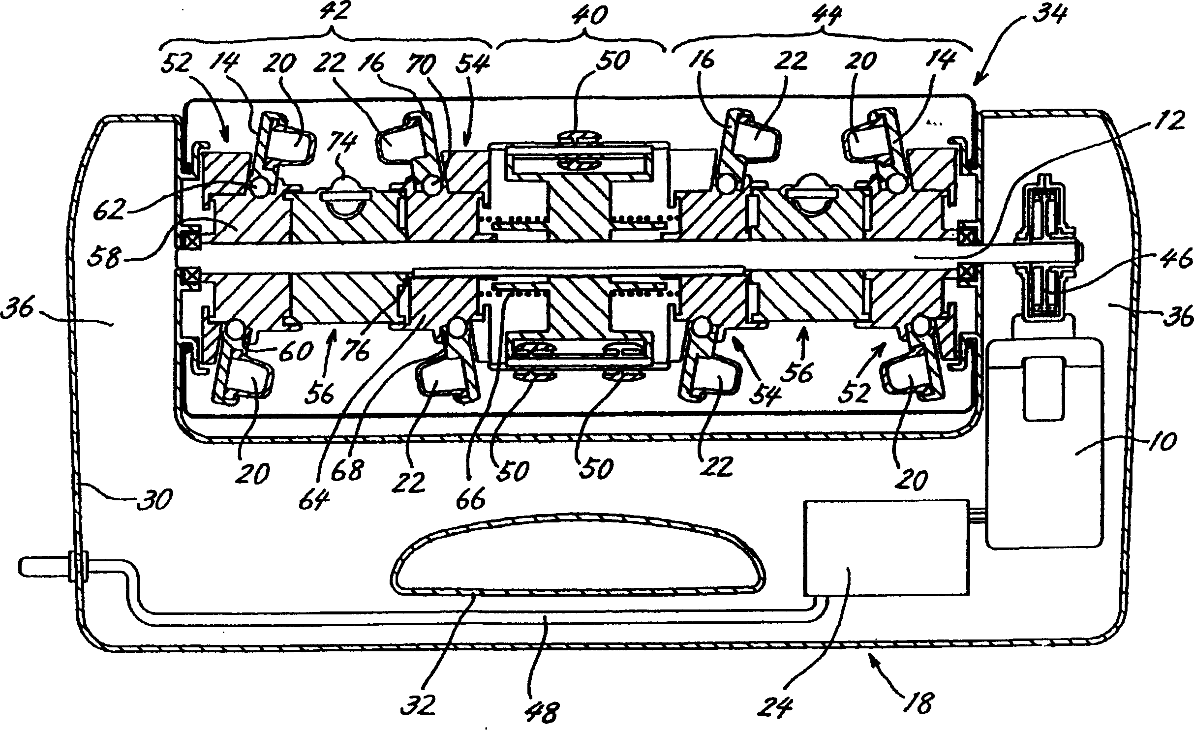
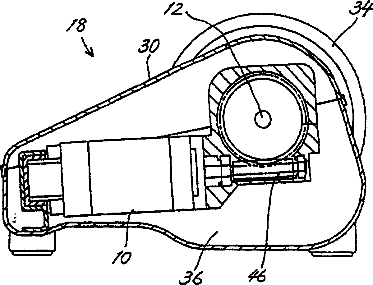
[0042] First, according to Figure 1 ~ Figure 3 , the structure of the massager 18 for realizing the present invention is described. Such as figure 1 and figure 2 As shown, the massager 18 is housed in a housing 30 formed of synthetic resin. In this casing 30, support portions 36, 36 for supporting a leg massage mechanism 34 protrude from both ends of the carrying handle 32 in the same direction.

[0043] A mechanism 34 for leg massage is arranged between the two supports 36 , 36 . This mechanism 34 comprises drive shaft 12, and this drive shaft is hinged on the supporting part 36,36; The rotary roller part 40 that is located in the middle of this drive shaft 12, the kneading roller 42 that is located at the both sides of rotary roller 40, 44. One end of the drive shaft 12 is connected to the electric motor 10 accommodated inside one of the support portions 36 through a reduction mechanism 46 . A control mechanism 24 that controls the motor 10 and a power cable 48 that ...


PUM


Abstract

A pair of disk shape treatment bodies 14 and 16 for massaging the lesion in the leg, or the like, of the person to be treated are fitted to a driving shaft 12 to be rotated by a motor 10 so as to be able to approach / separation in this massage machine. The machine is provided with a control means 24 having a detector 26 for detecting the change of the treatment strength to be added to him or her from the bodies 14 and 16 and having a control part 28 for adjusting the treatment strength onto him or her based on the detection value of the detector 26. The change of a load current in the motor 10 is indicated as an example for the detection value detected by the detector 26. Besides, the treatment strength on him or her is adjusted by changing the rotational speed of the motor 10.

Description

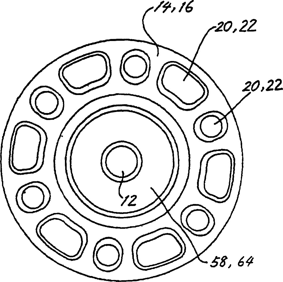
[0001] This application is a divisional application of China No. 01102276.0 patent application for invention. technical field [0002] The present invention relates to a massager for massaging affected parts such as legs, arms, and neck of a user receiving treatment, and a method for controlling the treatment force of the massager. Background technique [0003] As a massager that massages the feet, calves, thighs, etc., or the affected parts of the neck, etc., of the user by pinching and rubbing, the following types are known. figure 1 As shown, a pair of disc-shaped treatment bodies 14 and 16 inclined symmetrically are attached to a drive shaft 12 rotated by a motor 10 . figure 1 The illustrated massager 18 is symmetrically provided with disk-shaped treatment bodies 14 , 16 for each unit. [0004] On the opposite surfaces of the treatment body 14, 16, a plurality of acupressure parts 20, 22 are respectively arranged in a ring shape, and if the person receiving the treatmen...

Claims


Application Information

Patent Timeline
IPC IPC(8): A61H23/02A61H7/00A61H15/00
CPCA61H23/0254A61H2015/0021A61H2201/0196A61H2201/1215A61H2201/5058
Inventor 高马俊树食场安弘勇内隆博勘场一志中村尚
Owner SANYO ELECTRIC CO LTD
Learn More