Coolant valve system for internal combustion engine and method

a technology of internal combustion engine and cooling valve, which is applied in the direction of machines/engines, mechanical equipment, and non-fuel substance addition to fuel, etc., can solve the problem of less than optimal performance of the component under certain operating conditions

Active Publication Date: 2007-07-12
INT ENGINE INTPROP CO LLC
View PDF1 Cites 48 Cited by
  • Summary
  • Abstract
  • Description
  • Claims
  • Application Information

AI Technical Summary

Benefits of technology

This patented technology allows two different types of fluids - one fluid flows through both systems while another fluid passes into each other's space inside it when there are no changes made during operation. By controlling this process based on factors like temperature, pressure, etc., these technical improvements can improve efficiency and reduce emissions from engines that operate under varying loads over time.

Problems solved by technology

The technical problem addressed in this patent text is the need for optimal management of coolant circuits in internal combustion engines to prevent overheating of specific engine components and ensure optimal performance under various operating conditions.

Method used


Image

  • Coolant valve system for internal combustion engine and method
  • Coolant valve system for internal combustion engine and method
  • Coolant valve system for internal combustion engine and method

Examples


Embodiment Construction

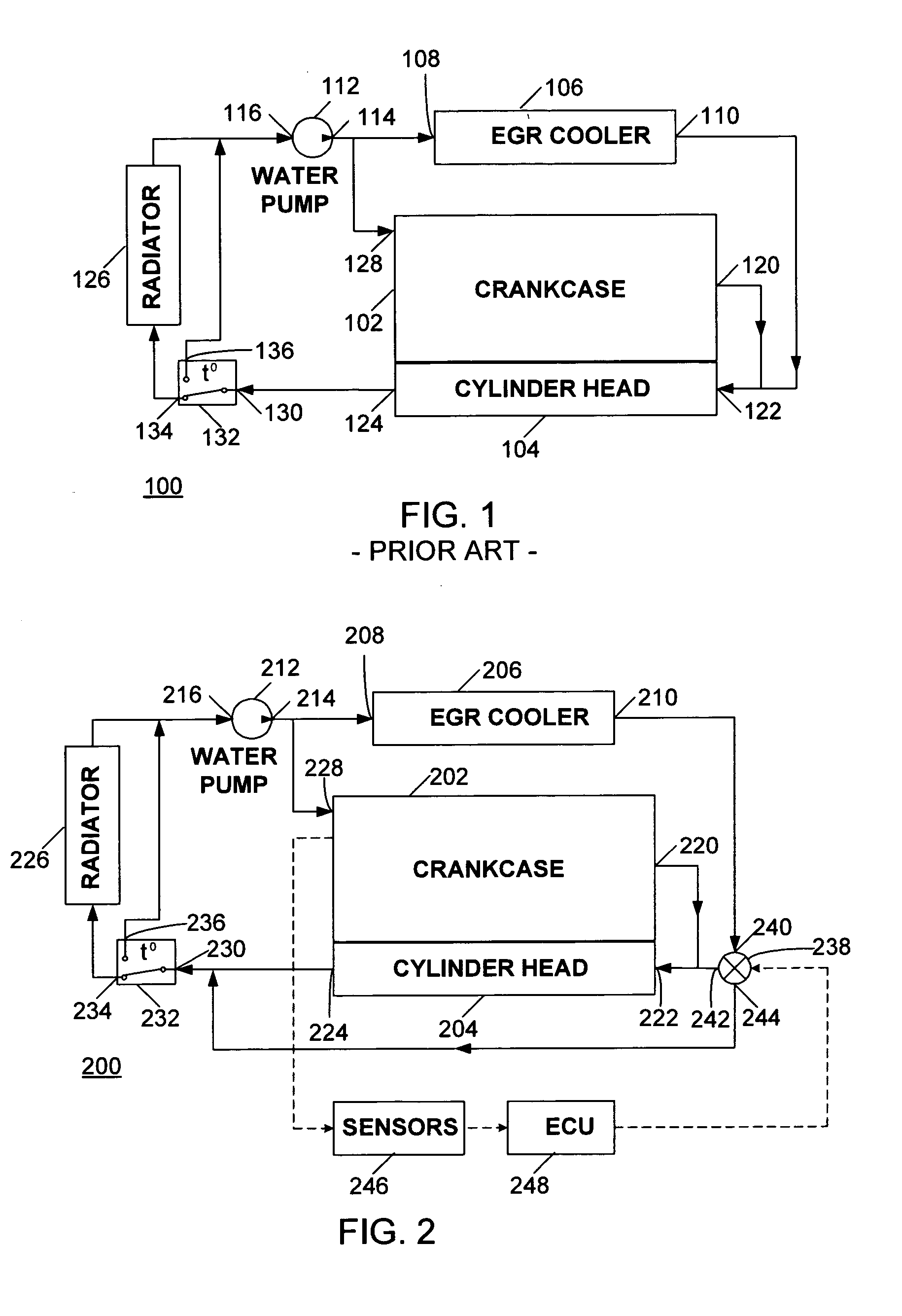
[0014] The following describes an apparatus for and method of management of coolant circuits in internal combustion engines that allows for optimal operation of an internal combustion engine. A prior art engine coolant circuit configuration is shown in FIG. 1. An engine 100 includes a crankcase 102 connected to a cylinder head 104. An EGR cooler 106 may be connected to the crankcase 102 of the engine 100 and has an EGR cooler inlet 108 and EGR cooler outlet 110. A water pump 112 has a pump inlet 116, and a pump outlet 114. The engine cooling circuit includes a coolant inlet 128 of the crankcase 102 that is fluidly connected to the pump outlet 114. A coolant outlet 120 from the crankcase 102 may be a port, but preferably is integrated with the crankcase 102 and is embodied in a plurality of openings that fluidly communicate with corresponding openings in the cylinder head 104. For the sake of clarity, the coolant outlet 120 is illustrated as a single port communicating with an extern...


PUM


Abstract

An internal combustion engine (200) includes a coolant pump (212) having a pump outlet (214), and a first exhaust gas recirculation (EGR) cooler (206) fluidly connected to the pump outlet (214). A crankcase (202) is fluidly connected in parallel with the EGR cooler (206) to the pump outlet (214) for receiving coolant therefrom. A cylinder head (204) is fluidly connected to the crankcase (202) for receiving coolant therefrom. A thermostat (232) is fluidly connected between the cylinder head (204) and the coolant pump (212). A valve system (238) has a first selectable position fluidly connecting the flow from the first EGR cooler (206) to the flow in the cylinder head (204), and a second selectable position fluidly connecting the flow from the first EGR cooler (206) to the thermostat (232) in bypassing relation to the cylinder head (204). Each of the first or second position is effected in response to an engine operating parameter.

Description


Claims


Application Information

Patent Timeline
Owner INT ENGINE INTPROP CO LLC
Why Eureka
Try Eureka