
Substrate adsorption device and substrate bonding device

a technology of substrate bonding and adsorption device, which is applied in the direction of work holders, manufacturing tools, instruments, etc., can solve the problems of increasing device cost, involving labor for exchanging stages, and increasing the size and variation of liquid crystal panels

Inactive Publication Date: 2007-07-12
SHARP KK
View PDF4 Cites 15 Cited by
  • Summary
  • Abstract
  • Description
  • Claims
  • Application Information

AI Technical Summary

Benefits of technology

[0020] The present invention has been made in view of the above problems and has its object of preventing a flaw on a substrate by detecting existence of a foreign matter, which is a factor of a flaw on the substrate, with a low-cost and simple construction of a substrate adsorption device for holding by adsorbing the substrate and a substrate bonding device provided therewith.
[0035] Moreover, the opening / closing mechanism is provided at each adsorption port of the air discharge path in combination with the pressure detecting means, which enables opening / closing of each adsorption port based on the detected pressure. Especially, when the opening / closing mechanism closes an adsorption port of which vacuum state is not detected by the pressure detecting means, leakage through the adsorption port stops. As a result, the substrate can be held securely at the other adsorption ports of which vacuum states are detected.
[0036] In addition, the formation of the leak trenches in a grid pattern or in a stripped pattern enables uniform detection of a foreign matter on the adsorption face.

Problems solved by technology

In this connection, the stage must be exchanged for respective different-sized substrates, which increases device cost and involves labor for exchanging the stages.
Recently, size and variation of the liquid crystal panels are increasing, and therefore, the above problem is significant in substrate adsorption devices for holding such liquid crystal panels.

Method used


Image

  • Substrate adsorption device and substrate bonding device
  • Substrate adsorption device and substrate bonding device
  • Substrate adsorption device and substrate bonding device

Examples


first embodiment

EFFECTS IN FIRST EMBODIMENT

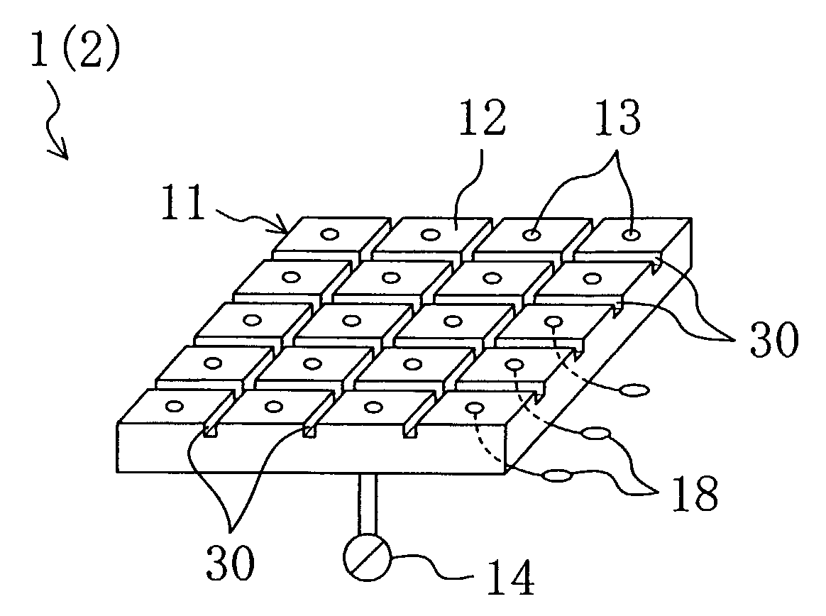
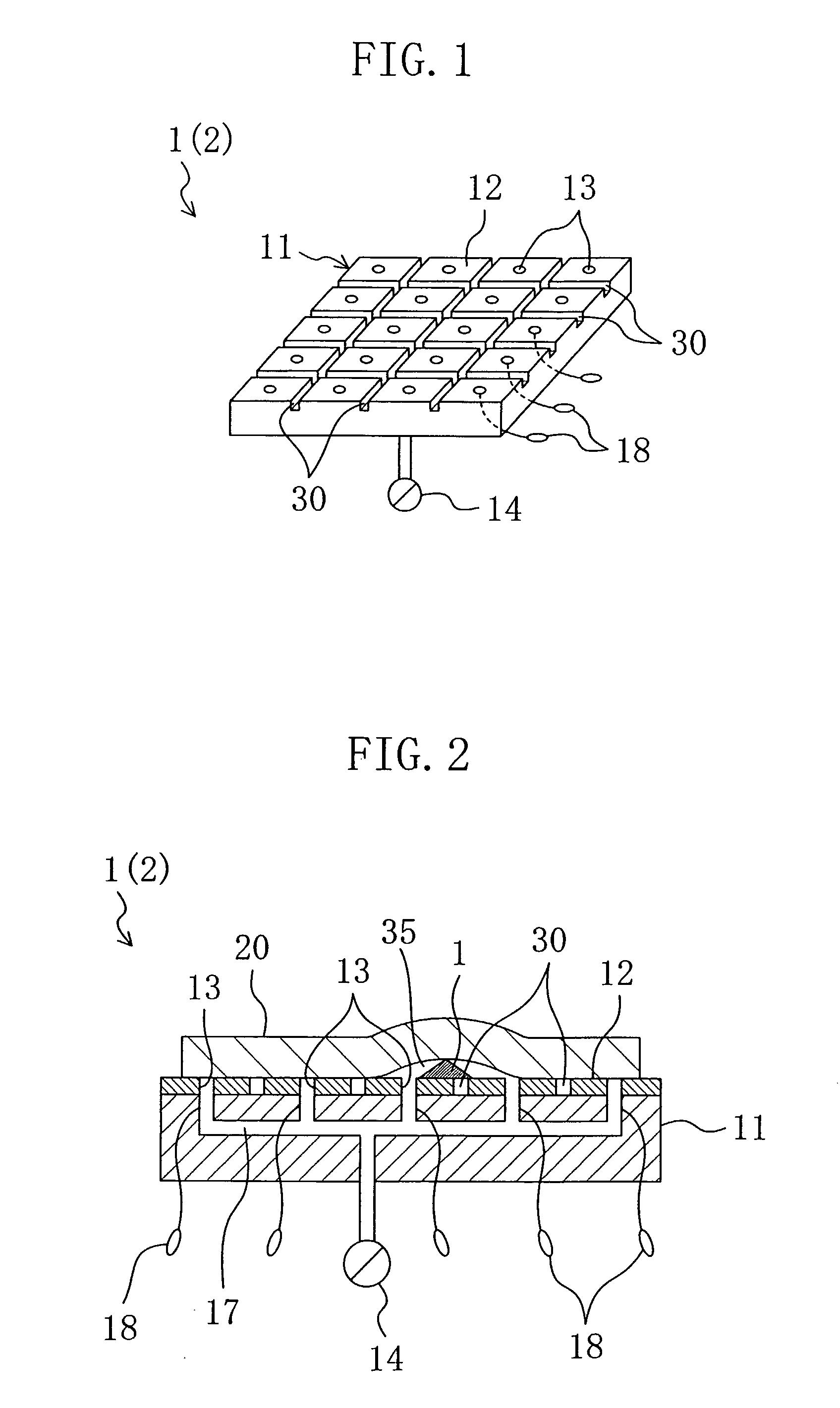
[0076] The size of the space 35 created around the foreign matter 15 between the substrate 20 and the adsorption face 12 depends on the relationship between the thickness of the substrate 20 and the size of the foreign matter 15 existing between the substrate 20 and the adsorption face 12, which is a factor of a flaw on the alignment film 21 and the substrate 20 itself. According to the present embodiment, interval setting of the leak trenches 30 and the like, taking the foregoing relationship in consideration, enables communication of the space 35 with both the adsorption ports 13 and the leak trenches 30.

[0077] Hence, the pressure in the air discharge path 17 can be made larger when the foreign matter 15 exists between the substrate 20 and the adsorption face 12 than when the foreign matter 15 does not exists therebetween by introducing air to the space 35 from the leak trenches 30 while discharging the air in the space 35 from the adsorption ports 13. ...

second embodiment

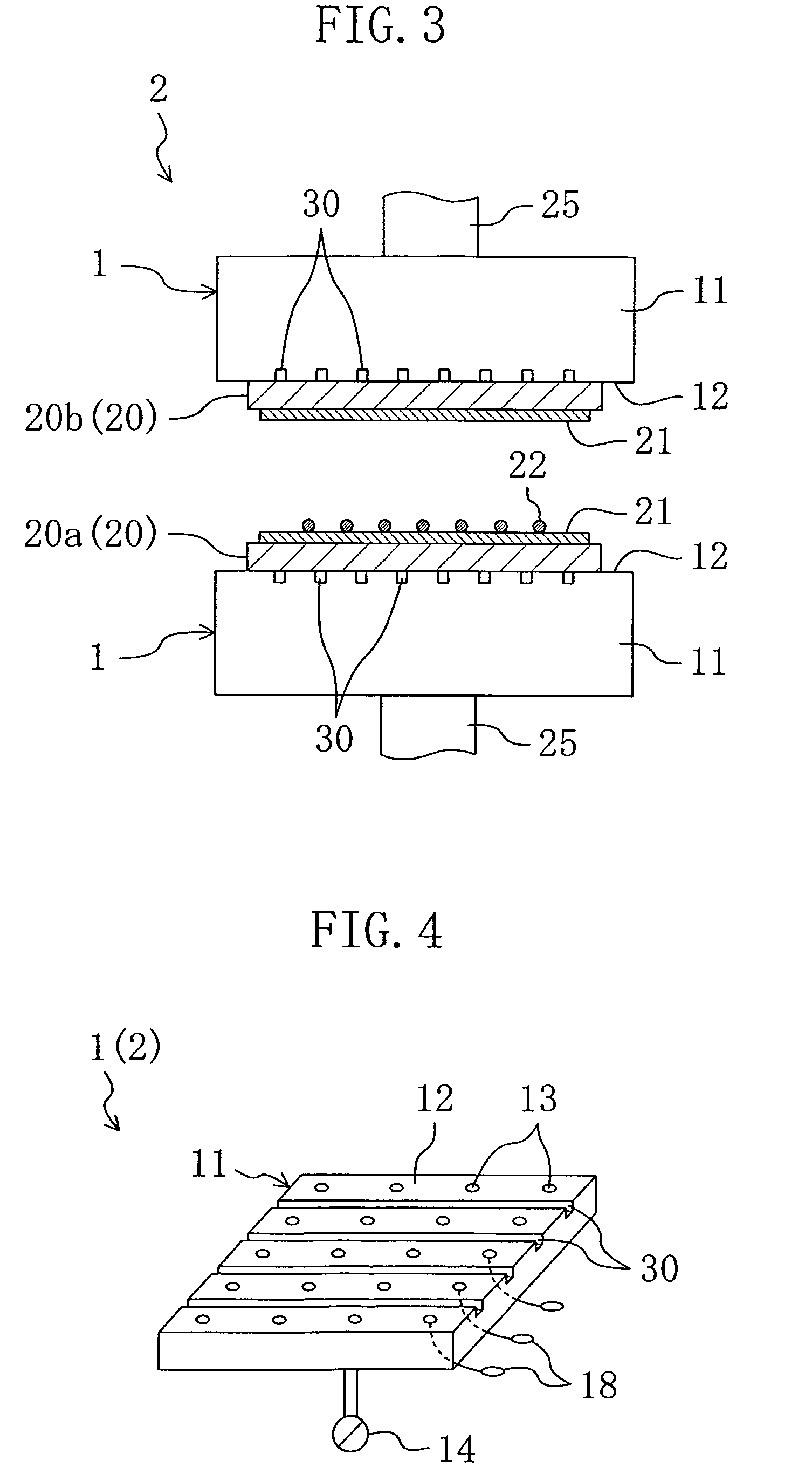
[0082]FIG. 4 shows the second embodiment according to the present invention. Wherein, the same reference numerals are assigned to the same members as in FIG. 1 through FIG. 3 and the detailed description thereof is omitted in the following embodiments.

[0083]FIG. 4 is a perspective view illustrating the stage 11 in the second embodiment. In the substrate adsorption devices 1 applied to the substrate bonding device 2 in the present embodiment, the leak trenches 30 are formed in a region of the adsorption face 12 in a stripped pattern, which is the feature.

[0084] In detail, the plural leak trenches 30 are formed in the stage 11 in parallel with one another at regular intervals. The plural adsorption ports 13 are arranged along the leak trenches 30 at regular intervals between the corresponding adjacent leak trenches 30. Each adsorption port 13 is formed at the center between the corresponding adjacent leak trenches 30. Thus, the formation of the leak trenches 30 in a stripped pattern...

third embodiment

[0085]FIG. 5 shows the third embodiment according to the present invention. In the present embodiment, valves 19 serving as an opening / closing mechanism are added to the substrate adsorption devices 1 in the first embodiment.

[0086] In detail, for each adsorption port 13, the pressure sensor 18 and a valve 19 for opening / closing the adsorption port 13 based on the pressure detected by the pressure sensor 18 are provided in the air discharge path 17, as show in FIG. 5. The valve 19 closes the corresponding adsorption port 13 when the corresponding pressure sensor 18 does not detect the vacuum state.

[0087] For adsorbing and holding the substrate 20 by the substrate adsorption device 1, the substrate 20 is placed on the adsorption face 12 of the stage 11 and the air between the substrate 20 and the adsorption face 12 is discharge from each adsorption port 13 through the air discharge path 17 in the same way as in the first embodiment.

[0088] If the foreign matter 15 exists between the...


PUM

PropertyMeasurementUnit
Pressureaaaaaaaaaa
Adsorption entropyaaaaaaaaaa

Abstract

A substrate adsorption device 1 includes: a stage 11 having an adsorption face 12 for holding a substrate 20; a plurality of adsorption ports 13 formed in a region of the adsorption face 12 of the stage 11; and a vacuum pump 14 connected to each adsorption port through an air discharge path 17. A pressure sensor 18 for detecting the pressure in the air discharge path 17 is provided, and a plurality of leak trenches 30 open to both the adsorption face 12 of the stage 11 and a side face of the stage 11 are formed in a region of the stage 11 except the region where the adsorption ports 13 are formed. With such a low-cost and simple structure, a foreign matter 15, which is a factor of inviting damage to the substrate 20, is detected, to prevent damage to the substrate 20.

Description

CROSS REFERENCE TO RELATED APPLICATIONS [0001] The disclosure of Japanese Patent Application No. 2004-009021 filed Jan. 16, 2004, including specification, drawings and claims is incorporated herein by reference in its entirety. TECHNICAL FIELD [0002] The present invention relates to a substrate adsorption device and a substrate bonding device including a stage for holding by adsorbing a substrate, and particularly relates to countermeasures for preventing malfunction caused due to the existence of a foreign matter between the stage and the substrate. BACKGROUND ART [0003] Conventionally, substrate adsorption devices for holding by adsorbing a substrate as an object to be processed to a flat stage have been known (see Patent Document 1 and Patent Document 2, for example.). [0004]FIG. 12 is a perspective view schematically illustrating the main portion of a substrate adsorption device 100, and FIG. 13 is a side view schematically illustrating a substrate bonding device 120 composed of...

Claims


Application Information

Patent Timeline
IPC IPC(8): B32B37/00H01L21/68B25B11/00G02F1/1333H01L21/00H01L21/683
CPCG02F2001/133354Y10T156/17H01L21/6838H01L21/67288G02F1/133354G02F1/13H01L21/68H01L21/683
Inventor MIYAKE, HIDETOMO
Owner SHARP KK
Learn More