Loop antenna and electronic equipment including loop antenna

Inactive Publication Date: 2007-07-12
FUJITSU LTD
View PDF2 Cites 75 Cited by
  • Summary
  • Abstract
  • Description
  • Claims
  • Application Information

AI Technical Summary

Benefits of technology

[0020] As mentioned above, the present invention can expand a communication range within which an IC card system including an IC chip and a loop antenna or electronic equipment having the IC chip and loop antenna

Problems solved by technology

Specifically, when the aforesaid loop antenna and IC chip are incorporated in portable electronic equipment such as a portable cellular phone, the loop antenna is susceptible to metal and, for example, the metallic part of a cell incorporated in the equipment.
(1) When only one loop antenna is incorporated together with an IC chip in a communication system, the detectable range offered by the communication system is limited.
(

Method used


Image

  • Loop antenna and electronic equipment including loop antenna
  • Loop antenna and electronic equipment including loop antenna
  • Loop antenna and electronic equipment including loop antenna

Examples


Embodiment Construction

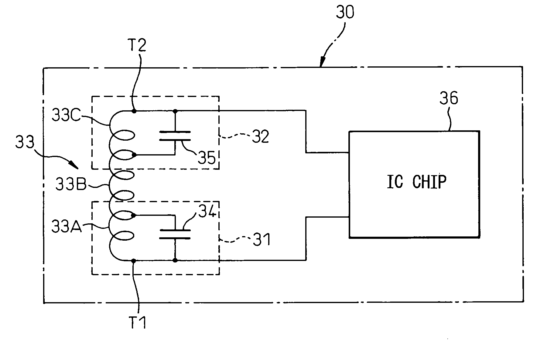
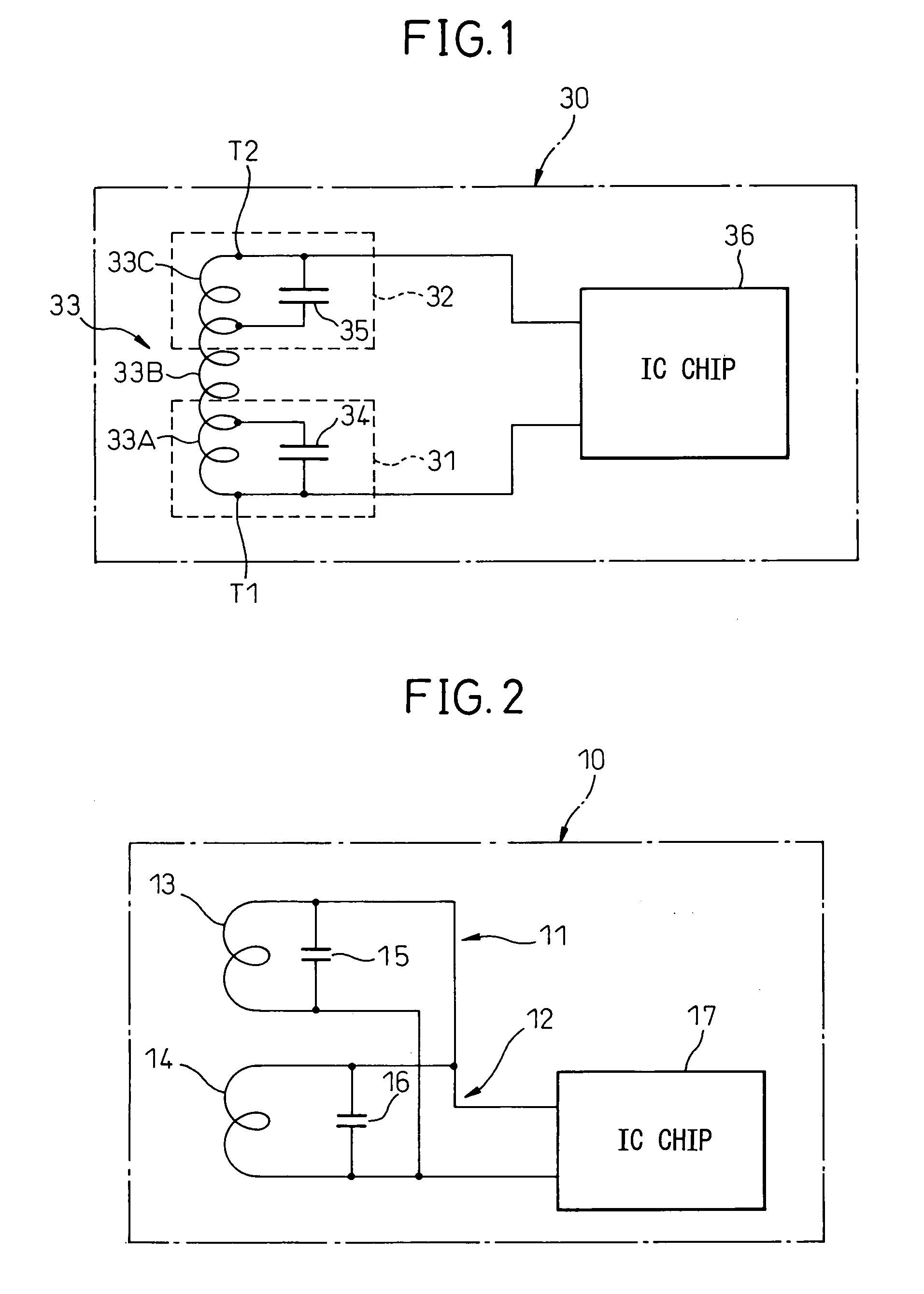
[0033] Before describing the preferred embodiments, an explanation will be given of the conventional IC card shown in FIG. 1.

[0034]FIG. 1 shows the internal circuitry of a conventional IC card 30 shown in FIG. 6 included in Japanese Unexamined Patent Application Publication No. 2000-269725. A loop antenna 33 is incorporated in the IC card 30 and has the taps T1 and T2 to an IC chip 36 made at both ends thereof. Moreover, the loop antenna 33 is divided into three portions 33A, 33B, and 33C due to intermediate taps T3 and T4. A first capacitor 34 is connected to the first portion 33A of the loop antenna 33, whereby a first resonant circuit 31 is formed. The second portion 33B has no connection. A second capacitor 35 is connected to the third portion 33C, whereby a second resonant circuit 32 is formed. The resonant frequencies of the first and second resonant circuits 31 and 32 respectively may be differentiated from each other by varying the capacitances of the capacitors 34 and 35. ...


PUM


Abstract

The present invention is intended to improve the receiving performance of a loop antenna to be connected to an IC chip that is incorporated in an IC card or a portable cellular phone. A loop antenna that is connected to an IC chip which has a CPU and a memory mounted thereon and which is incorporated in a casing, and that transmits or receives predetermined electromagnetic waves to or from a reader writer includes a main loop antenna and at least one sub-loop antenna disposed away from the main loop antenna. The sub-loop antenna is connected to the IC chip in parallel with or in series with the main loop antenna. A transmission/reception frequency at which the sub-loop antenna transmits or receives electromagnetic waves may be different from the one at which the main loop antenna transmits or receives electromagnetic waves.

Description

CROSS-REFERENCE TO RELATED APPLICATION [0001] This application claims priority from, and incorporates by reference the entire disclosure of, Japanese Patent application No. 2005-361681 filed on Dec. 15, 2005. BACKGROUND OF THE INVENTION [0002] 1. Field of the Invention [0003] The present invention relates to a loop antenna and electronic equipment including the loop antenna. More particularly, the present invention is concerned with a loop antenna to be adapted to a device in or from which data is written or read in a non-contact manner, such as an IC card, and electronic equipment including the loop antenna, such as a portable cellular phone. [0004] 2. Description of the Related Art [0005] In recent years, IC cards, having a built-in IC in which information such as data of receipts and payments of money can be stored, have prevailed. Information on a commuter pass, a role of an IC card, and information on stations at which a user of the IC card gets on or off are stored in the IC c...

Claims


Application Information

Patent Timeline
IPC IPC(8): G06K19/06
CPCG06K19/0723H01Q7/00H01Q1/2225G06K19/07749
Inventor FUKUDA, TOSHINARIOGINO, MANABUNIKAWA, SUSUMU
Owner FUJITSU LTD
Why Eureka
Try Eureka