Light emitting apparatus

Inactive Publication Date: 2007-07-12
CANON KK
View PDF25 Cites 11 Cited by
  • Summary
  • Abstract
  • Description
  • Claims
  • Application Information

AI Technical Summary

Benefits of technology

[0015] With that arrangement, it is possible to damp the impact and stress applied to the protective plate by the filler, and to avoid breakage of the light emitting device.
[0016] If air is filled in the space between the protective layer formed in the light emitting device and the protective plate, extraneous light is reflected at the interface between the prote

Problems solved by technology

Even in the state of the organic EL device being supported by the housing, when an impact is externally applied (e.g., when an operator hits a display surface against some hard object), the organic EL device may be damaged or broken.
In such a structure, when an impac

Method used


Image

  • Light emitting apparatus
  • Light emitting apparatus
  • Light emitting apparatus

Examples


first embodiment

[0035] A light emitting apparatus according to a first embodiment of the present invention is featured in that the light emitting apparatus includes a light emitting device, a housing, and a protective plate, and that a filler is disposed in a space between the light emitting device and the protective plate.

[0036] With those features, stress externally applied to the protective plate is damped by the filler and the light emitting device is protected from being broken or damaged.

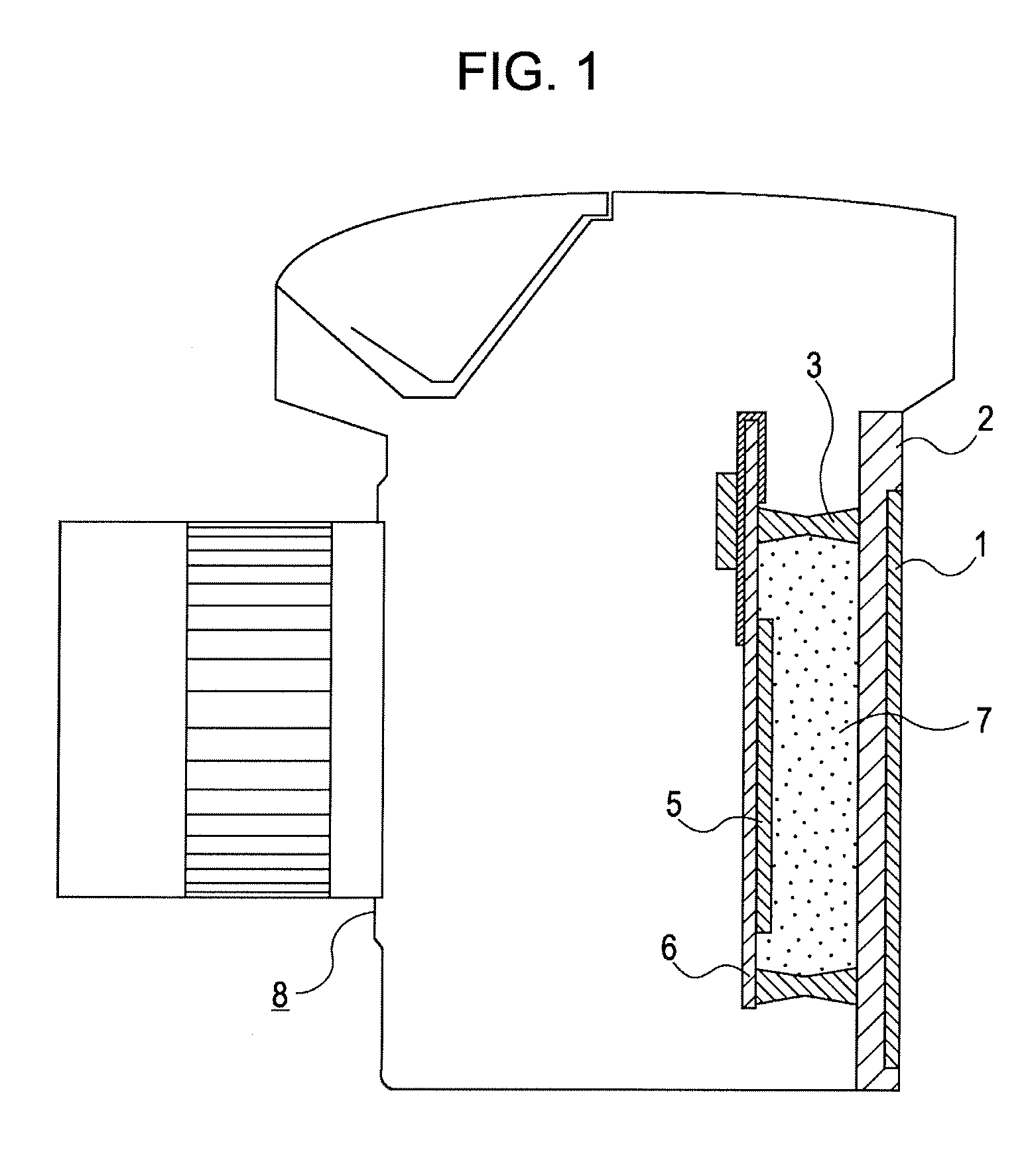
[0037]FIG. 1 is a schematic view, partly sectioned, of a digital camera in which the light emitting apparatus according to the first embodiment of the present invention is employed as an image pickup apparatus.

[0038] Reference numerals 1 denotes a protective plate, 2 denotes a housing, 3 denotes a side wall, 5 denotes a light emitting device, 6 denotes a base member, 7 denotes a filler, and 8 denotes the entire digital camera. The light emitting apparatus is used, in this non-limiting example, in a display...

second embodiment

[0069] A light emitting apparatus according to a second embodiment of the present invention is featured in that an antireflective layer is disposed between a protective layer and a protective plate. The other construction is the same as that of the first embodiment.

[0070]FIG. 3 is a schematic view, partly sectioned, of a digital camera in which the light emitting apparatus according to the second embodiment of the present invention is employed as an image pickup apparatus.

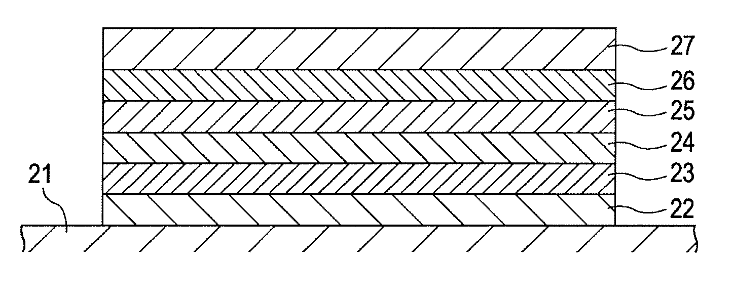
[0071] In FIG. 3, an antireflective layer 4 is shown as being disposed in contact with the light emitting device 5. More specifically, since the light emitting device 5 has a protective layer at the top thereof, the antireflective layer 4 is disposed on the protective layer in this second embodiment. With such an arrangement that the antireflective layer is disposed between the protective layer and the protective plate, since the antireflective layer is positioned closer to the light taking-out side than the prot...


PUM


Abstract

A light emitting apparatus which can protect a light emitting device from external stress, etc. The light emitting apparatus includes a light emitting device, a housing, and a protective plate. A filler is disposed in a space between the light emitting device and the protective plate.

Description

BACKGROUND OF THE INVENTION [0001] 1. Field of the Invention [0002] The present invention relates to a light emitting apparatus including a housing and a light emitting device, such as an organic light emitting device (organic EL (electroluminescent) device), which has a light emitting layer disposed between a pair of electrodes. [0003] 2. Description of the Related Art [0004] A display using an organic EL device in a display portion is developed. [0005] Patent Document 1 (Japanese Patent Laid-Open No. 2001-100641) discloses a light emitting apparatus including an organic EL device. The organic EL device containing a pixel electrode, a light emitting layer, and a counter (common) electrode is supported by a housing. [0006] Even in the state of the organic EL device being supported by the housing, when an impact is externally applied (e.g., when an operator hits a display surface against some hard object), the organic EL device may be damaged or broken. [0007] According to Patent Doc...

Claims


Application Information

Patent Timeline
IPC IPC(8): H05B33/00
CPCH01L51/5237H10K50/841H10K50/858H10K50/86H10K50/87
Inventor YUKI, OSAMUMORI, HIDEOISOBE, RYUICHIROOSATO, YOICHIKITAYAMA, HIROYUKIHASEGAWA, TOSHINORI
Owner CANON KK
Why Eureka
Try Eureka