
Magnification engine

a technology of magnification engine and display path, which is applied in the field of graphics magnification system and method, can solve the problems of reducing content security, affecting magnification operations, and not having unlimited access to information, so as to increase the security of proprietary information in the display path, and achieve easy and stably effect magnification operations

Inactive Publication Date: 2007-07-12
MICROSOFT TECH LICENSING LLC
View PDF19 Cites 19 Cited by
  • Summary
  • Abstract
  • Description
  • Claims
  • Application Information

AI Technical Summary

Benefits of technology

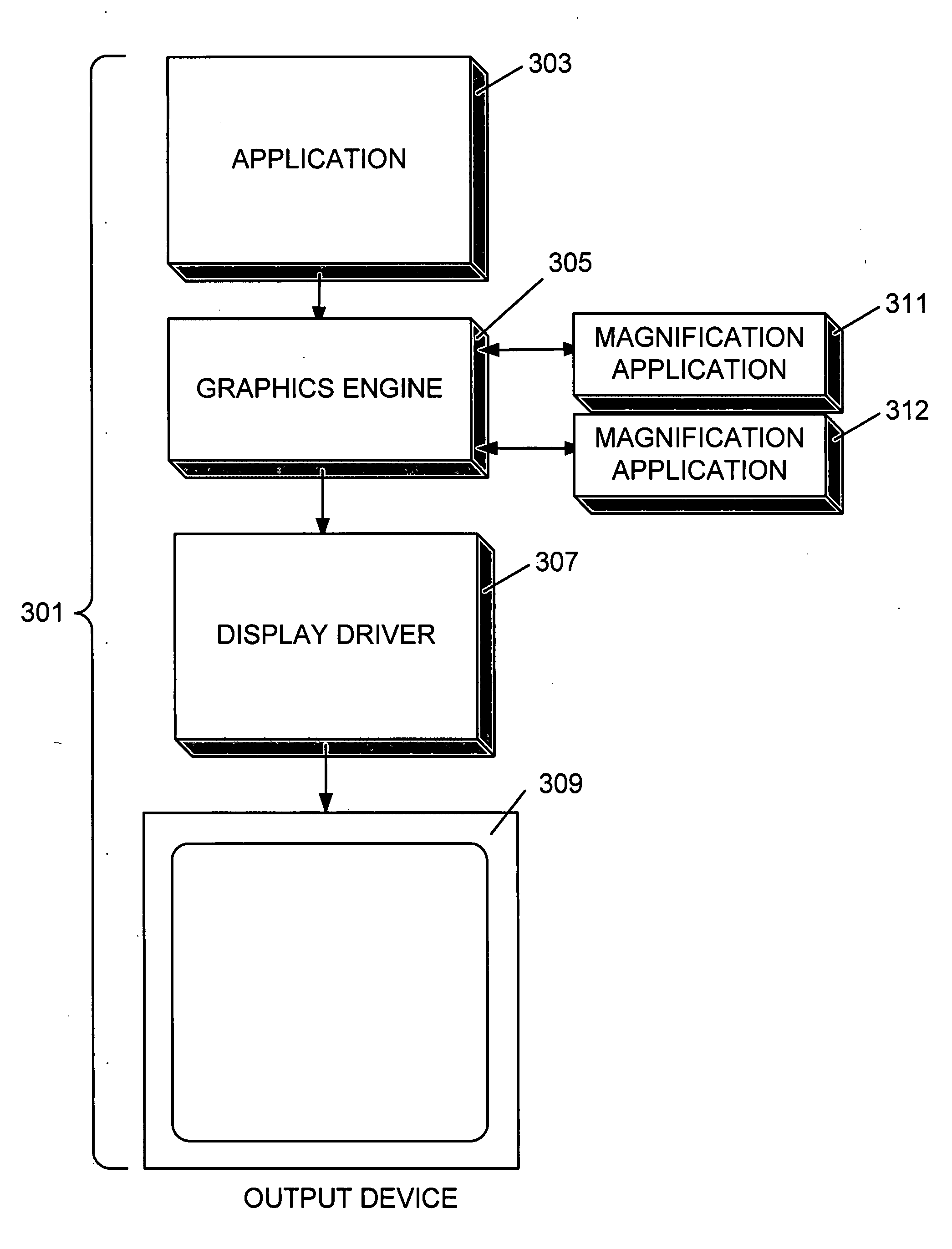
The patent describes a system and method for enhancing the accessibility of computer systems for visually handicapped or impaired users. The system uses a graphics engine to modify the final output image based on magnification parameters received from magnification applications. The modified image is then passed to a driver or other entity for rendering or display via output hardware such as a screen or printer. The system also performs compositing to display both magnified and unmagnified content together in the image output. This increases security of proprietary information in the display path and makes the display path more resistant to malicious tampering. The output format can be determined by the compositor of the graphics engine or by user input. The technical effects of the invention include improving accessibility for visually handicapped or impaired users and increasing flexibility for magnification application manufacturers.

Problems solved by technology

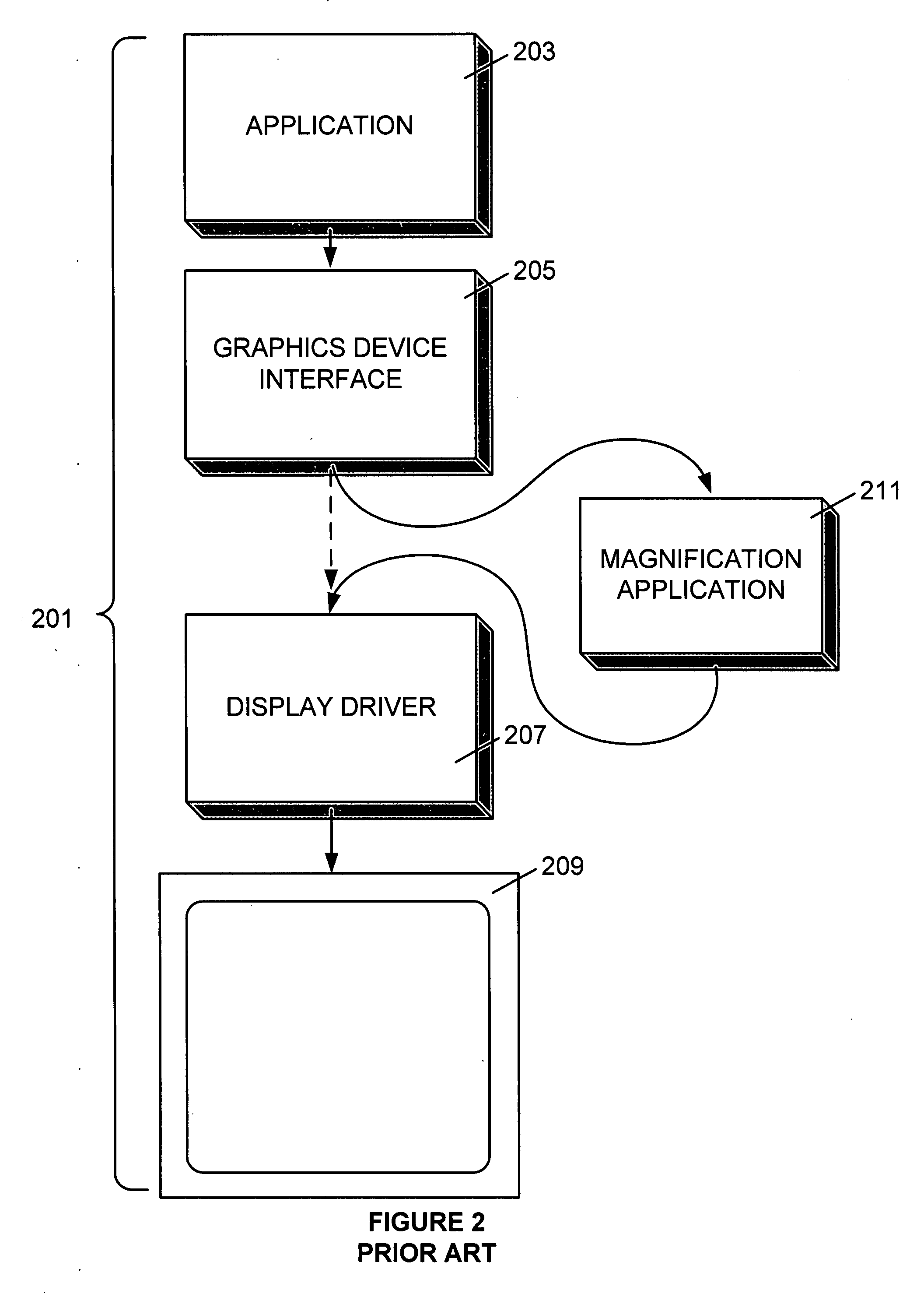
In this manner, magnification applications can direct and affect the display path but do not have unlimited access to the information in the display path.
This embodiment decreases content security and also makes the display path more susceptible to malicious tampering.

Method used


Image

  • Magnification engine
  • Magnification engine
  • Magnification engine

Examples


Embodiment Construction

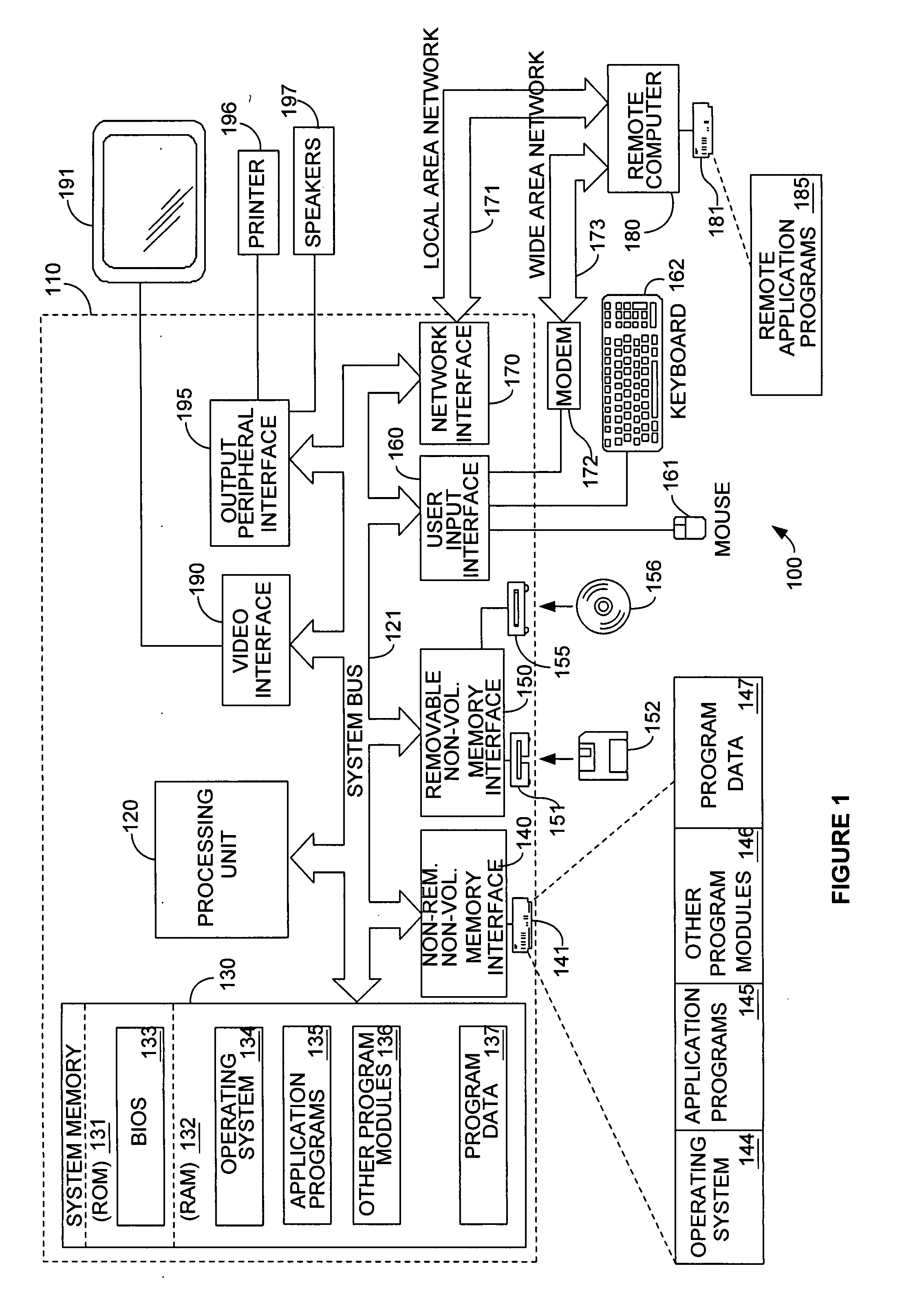
[0020] Turning to the drawings, wherein like reference numerals refer to like elements, the invention is illustrated as being implemented in a suitable computing environment. Although not required, the invention will be described in the general context of computer-executable instructions, such as program modules, being executed by a personal computer. Generally, program modules include routines, programs, objects, components, data structures, etc. that perform particular tasks or implement particular abstract data types. Moreover, those skilled in the art will appreciate that the invention may be practiced with other computer system configurations, including hand-held devices, multi-processor systems, microprocessor based or programmable consumer electronics, network PCs, minicomputers, mainframe computers, and the like. The invention may be used in a networked environment and may further be practiced in distributed computing environments wherein tasks are performed by remote proces...


PUM


Abstract

An improved graphics processing system and method are described for magnifying visual output information for printing, display, or other output. A graphics engine transforms display information so as to magnify one or more components or areas of an output image for display via output hardware such as a screen or printer. Magnification parameters are supplied to the graphics engine by one or more magnification applications. In an embodiment of the invention, the graphics engine performs compositing of magnified and unmagnified content for display. In an alternative embodiment, the graphics engine outputs corresponding scaled image material to the appropriate magnification application for rendering. In a further embodiment, the graphics engine may operate in both modes. The magnified output according to various embodiments of the invention enhances the accessibility of the computer system for visually handicapped or impaired users by providing high quality magnification and increased system and application stability.

Description

RELATED APPLICATION [0001] This application is a Division of U.S. application Ser. No. 10 / 253,680 entitled “Magnification Engine” filed Sep. 24, 2002, which is incorporated herein by reference.TECHNICAL FIELD [0002] This invention relates generally to the technology of computer graphics output generation and, more particularly, relates to a system and method for graphics magnification. BACKGROUND OF THE INVENTION [0003] Computers, once thought to be the lone province of hobbyists and governments, have become an integral part of many people's lives. With the advent of friendly user interfaces, ample memory, high-speed processors, and network technologies, many everyday tasks can be accomplished much more easily via a computer. Indeed, for some tasks a computer is mandatory. Despite the increasing prevalence of computer use, the user interface aspects of many computer systems are not well suited to certain classes of users. For example, visually impaired users may have great difficult...

Claims


Application Information

Patent Timeline
Patent Type & Authority Applications(United States)
IPC IPC(8): G09G5/00G06T3/40
CPCG06T3/40
Inventor SINCLAIR, ROBERT E. IIMCKEON, BRENDAN
Owner MICROSOFT TECH LICENSING LLC
Learn More