
Thin film magnetic head and method for manufacturing the same

Inactive Publication Date: 2007-07-12
JAPAN SCI & TECH CORP +1
View PDF12 Cites 14 Cited by
  • Summary
  • Abstract
  • Description
  • Claims
  • Application Information

AI Technical Summary

Benefits of technology

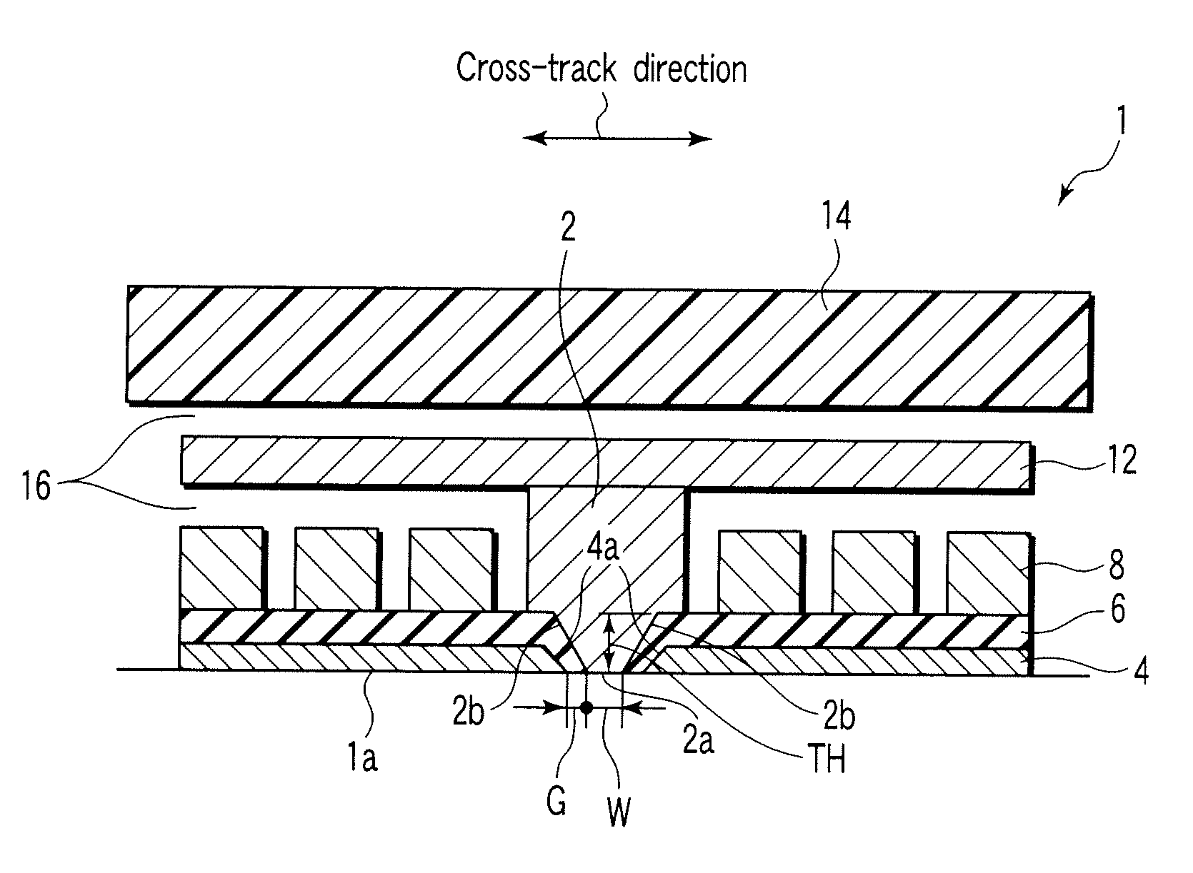
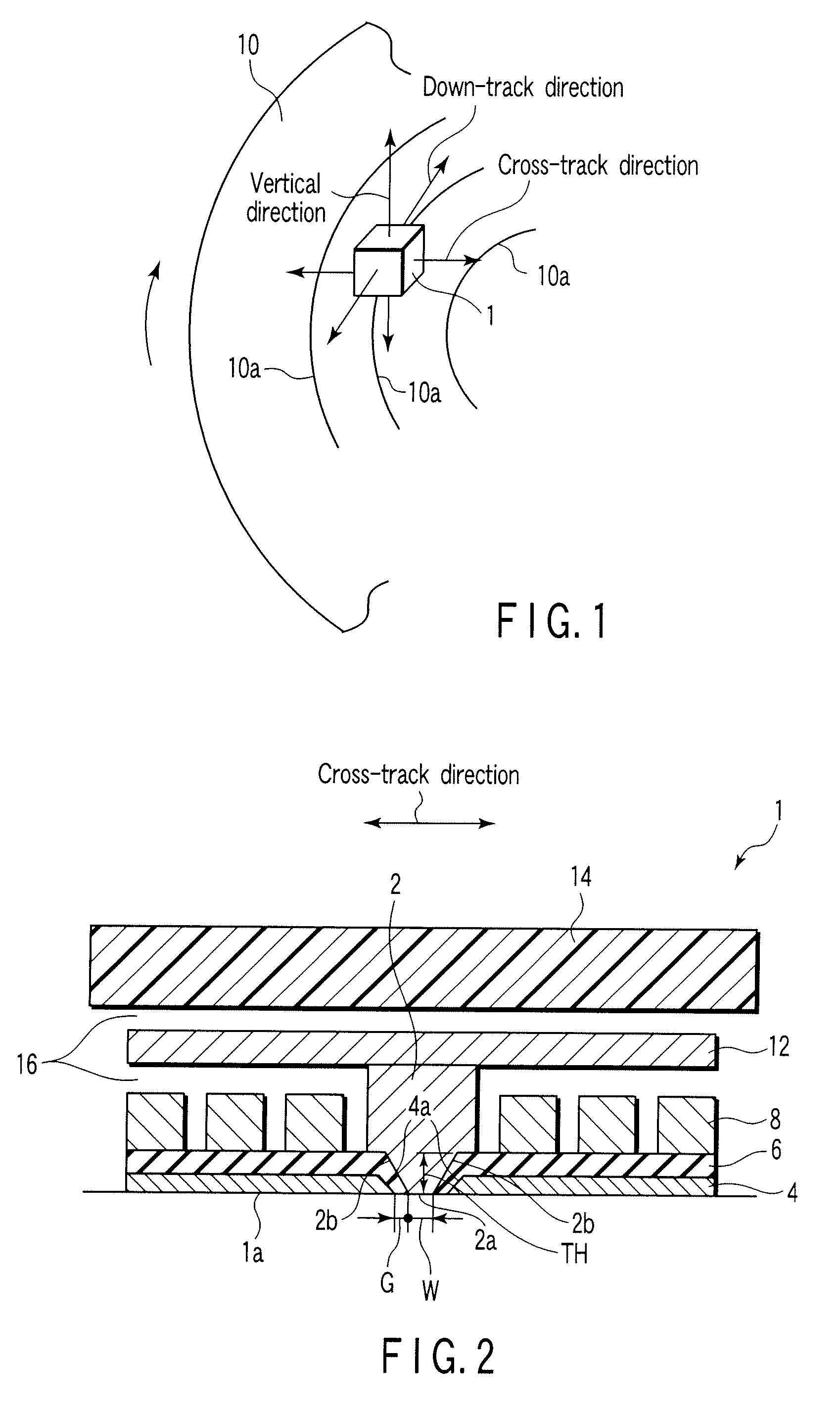
[0010] It is an object of the present invention to provide a thin film magnetic recording head and a method for manufacturing the magnetic recording head that is capable of forming a steep and strong recording field and enhancing a recording density. To achieve the object, a thin film magnetic recording head according to the present invention comprises an opposite face opposite to a recording track of a magnetic recording medium; a main pole having a distal end exposed to the opposite face; a shield yoke extending the opposite face, and provided in a non-contact state via a predetermined gap on the main pole; and a coil to form a recording field which is generated at the magnetic recording medium from a distal end of the main pole; the main pole, the shield yoke, and the coil being formed to be substantially in parallel to the opposite face, wherein, in the vicinity of the distal end of the main pole, side faces at both ends in a widthwise direction of the recording track and a side face of at least one end in the recording track direction are inclined outwardly in a direction distant from the distal end.
[0014] According to the invention described above, a main pole having an inclined side face and a shield yoke having an inclined end face that is opposed to the side face of the main pole via a predetermined gap can be formed in accordance with a simple process, i.e., by merely depositing and forming as a film a magnetic material or an insulation material on a surface of a substrate in an unidirectional manner; and TH of the main pole, a width of a distal end of the main pole exposed to an opposite face, SH of the shield yoke, and a gap therebetween can be formed with high dimensional precision.

Problems solved by technology

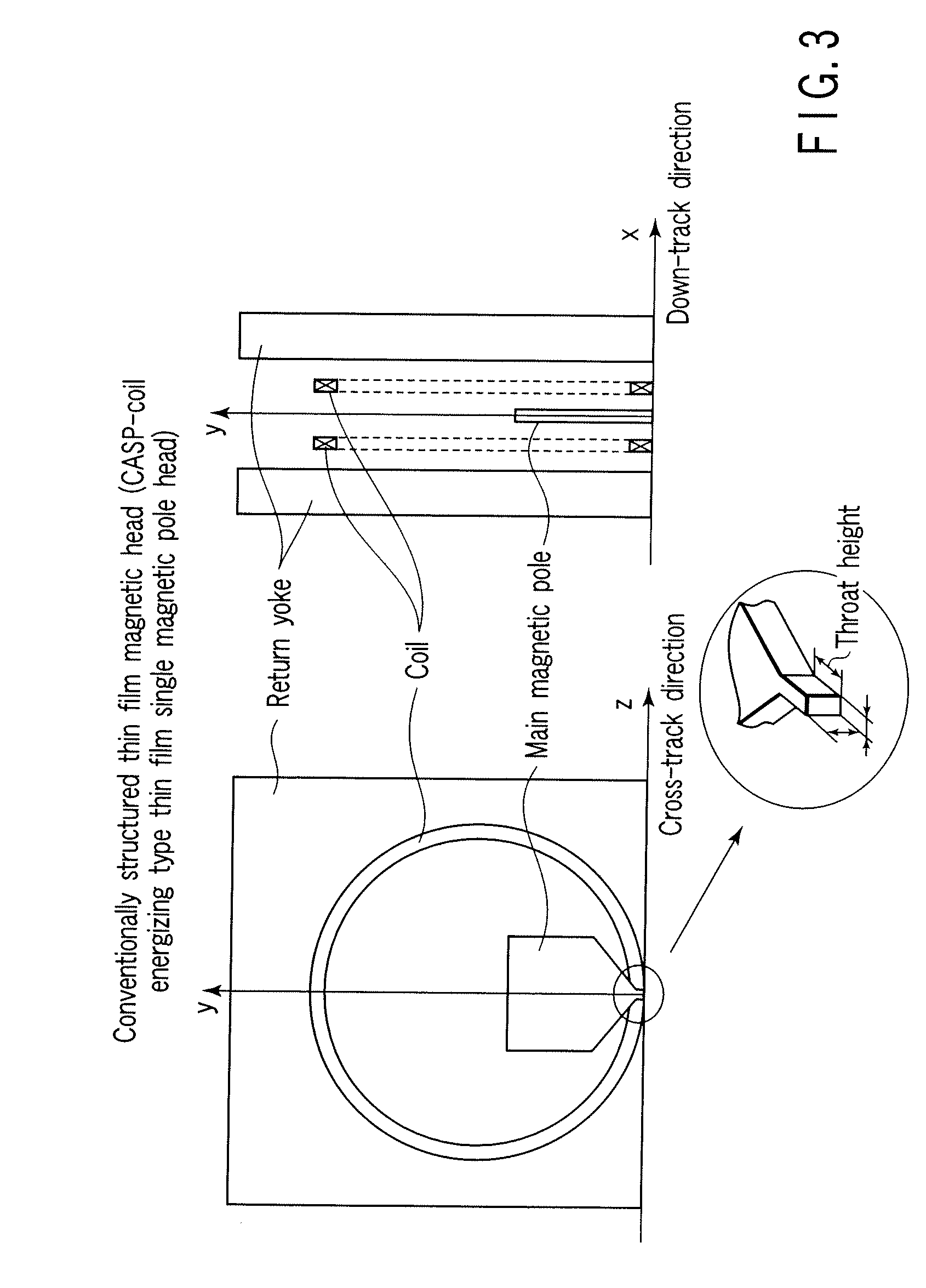
However, at present, there is no specific report relevant to a method for manufacturing the taper and TH of the main pole, SH of the side shield, or a head capable of achieving a narrow gap as described in the above report, and a magnetic head having sufficiently satisfactory recording characteristics has not been successfully manufactured.

Method used


Image

  • Thin film magnetic head and method for manufacturing the same
  • Thin film magnetic head and method for manufacturing the same
  • Thin film magnetic head and method for manufacturing the same

Examples


Embodiment Construction

[0047] Hereinafter, embodiments of the present invention will be described in detail with reference to the accompanying drawings.

[0048]FIG. 1 shows a schematic view of a so-called horizontal (planar) thin film single pole type magnetic recording head 1 (hereinafter, simply referred to as a head 1) that serves as a thin film magnetic recording head according to an embodiment of the present invention. The head 1 is provided to be movable along a surface of a magnetic recording disk 10 (hereinafter, merely referred to as a disk 10) so as to be opposed to a desired recording track 10a of the disk 10 that serves as a magnetic recording medium. In the following description, a direction taken along the recording track 10a to which the head 1 is opposed is referred to as a down-track direction; a widthwise direction of the recording track 10a (i.e., radial direction of the disk 10) is referred to as a cross-track direction; and a direction distant from the recording track 10a (disk 10) is ...


PUM

PropertyMeasurementUnit
Thicknessaaaaaaaaaa
Antiferromagnetismaaaaaaaaaa
Poweraaaaaaaaaa

Abstract

A magnetic head has an opposite face opposite to a magnetic disk, a main pole having a distal end face and an inclined face exposed to the opposite face, and a shield yoke extended substantially facing the opposite face. An end face on which the shield yoke is opposite to the main pole via a gap is inclined substantially in parallel to the inclined face of the main pole.

Description

CROSS-REFERENCE TO RELATED APPLICATIONS [0001] This is a Continuation Application of PCT Application No. PCT / JP2005 / 023169, filed Dec. 16, 2005, which was published under PCT Article 21(2) in Japanese. [0002] This application is based upon and claims the benefit of priority from prior Japanese Patent Application No. 2004-364926, filed Dec. 16, 2004, the entire contents of which are incorporated herein by reference.BACKGROUND OF THE INVENTION [0003] 1. Field of the Invention [0004] The present invention relates to a thin film magnetic head for magnetically recording information in a magnetic recording medium and a method for manufacturing the magnetic head, and particularly to a thin film magnetic head and a method for manufacturing the magnetic head incorporated in a hard disk drive (HDD) mounted in a personal computer or mobile equipment, for example. [0005] 2. Description of the Related Art [0006] In recent years, there has been made a report based on magnetic field analysis and c...

Claims


Application Information

Patent Timeline
IPC IPC(8): G11B5/147G11B5/127
CPCG11B5/3116Y10T29/49037G11B5/3163G11B5/313
Inventor YAMAKAWA, KIYOSHIYAMADA, HIDETAKATAKAHASHI, SHINGOISE, KAZUYUKI
Owner JAPAN SCI & TECH CORP
Learn More