
Loudspeaker system

a loudspeaker and speaker technology, applied in the field of loudspeaker systems, can solve the problems of affecting the quality of voice, and affecting the sound quality of human speakers, and achieve the effect of high-quality voice amplification

Active Publication Date: 2007-07-12
YAMAHA CORP
View PDF6 Cites 30 Cited by
  • Summary
  • Abstract
  • Description
  • Claims
  • Application Information

AI Technical Summary

Benefits of technology

[0011] It is an object of the present invention to provide a hands-free loudspeaker system which is capable of achieving high-quality voice amplification without requiring a human speaker to move to a microphone or a microphone to be moved to a human speaker.
[0014] Further, it is possible to suppress interference and variation in a receiving condition, which can often be caused when using a wireless microphone, and prevent leakage of information.
[0015] Furthermore, even if a human speaker's location shifts from one place to another e.g. during a question-and-answer session, it is not necessary to manually switch between microphones, which eliminates the need to employ operators.
[0016] Moreover, since a microphone closest to the current human speaker's location is selected, the loop gain can be improved, which makes it possible not only to prevent occurrence of howling, but also to ensure voice clarity.

Problems solved by technology

Further, a reproduction system, which is generally comprised of loudspeakers in a centralized arrangement or loudspeakers disposed on a ceiling in a dispersed arrangement, suffers from problems.
In the case where a wired microphone is to be moved, it is necessary to take care of a microphone cable, which troubles a human speaker a lot.
On the other hand, as for a wireless microphone, the Radio Law provides that acquisition of a license or registration is required, and the consumer band suffers from the problems of interference and wiretapping (leakage of information).
Furthermore, when a plurality of microphones are used, reduction of a loop gain per system makes it difficult to suppress howling and maintain voice clarity and sound quality.

Method used


Image

  • Loudspeaker system
  • Loudspeaker system
  • Loudspeaker system

Examples


Embodiment Construction

[0030] A preferred embodiment of the present invention will be described in detail below with reference to the drawings.

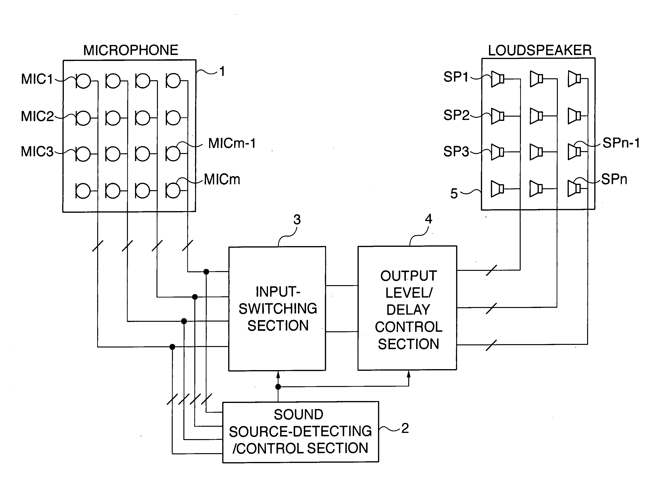
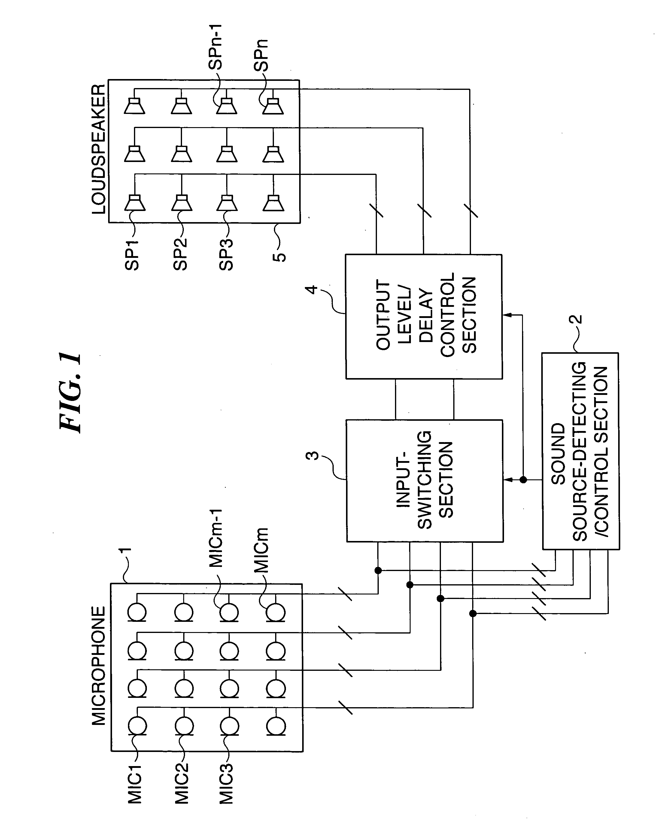
[0031]FIG. 1 is a schematic block diagram of a loudspeaker system according to the embodiment of the present invention.

[0032] In FIG. 1, reference numeral 1 designates a plurality of (m) microphones dispersedly arranged e.g. on the ceiling of a conference room or a hall where the loudspeaker system of the present invention is installed, and reference numeral 5 designates a plurality of (n) loudspeakers also dispersedly arranged e.g. on the ceiling. Each of the microphones 1 (MIC1 to MICm) has a directivity limited to collect sounds only in an area in the vicinity thereof, and the whole room is covered by the m microphones dispersedly arranged on the ceiling. Similarly, each of the loudspeakers 5 (SP1 to SPn) can be configured to have a directivity limited to output sounds only to an area in the vicinity thereof, and the whole room can be covered by the n loudspea...


PUM


Abstract

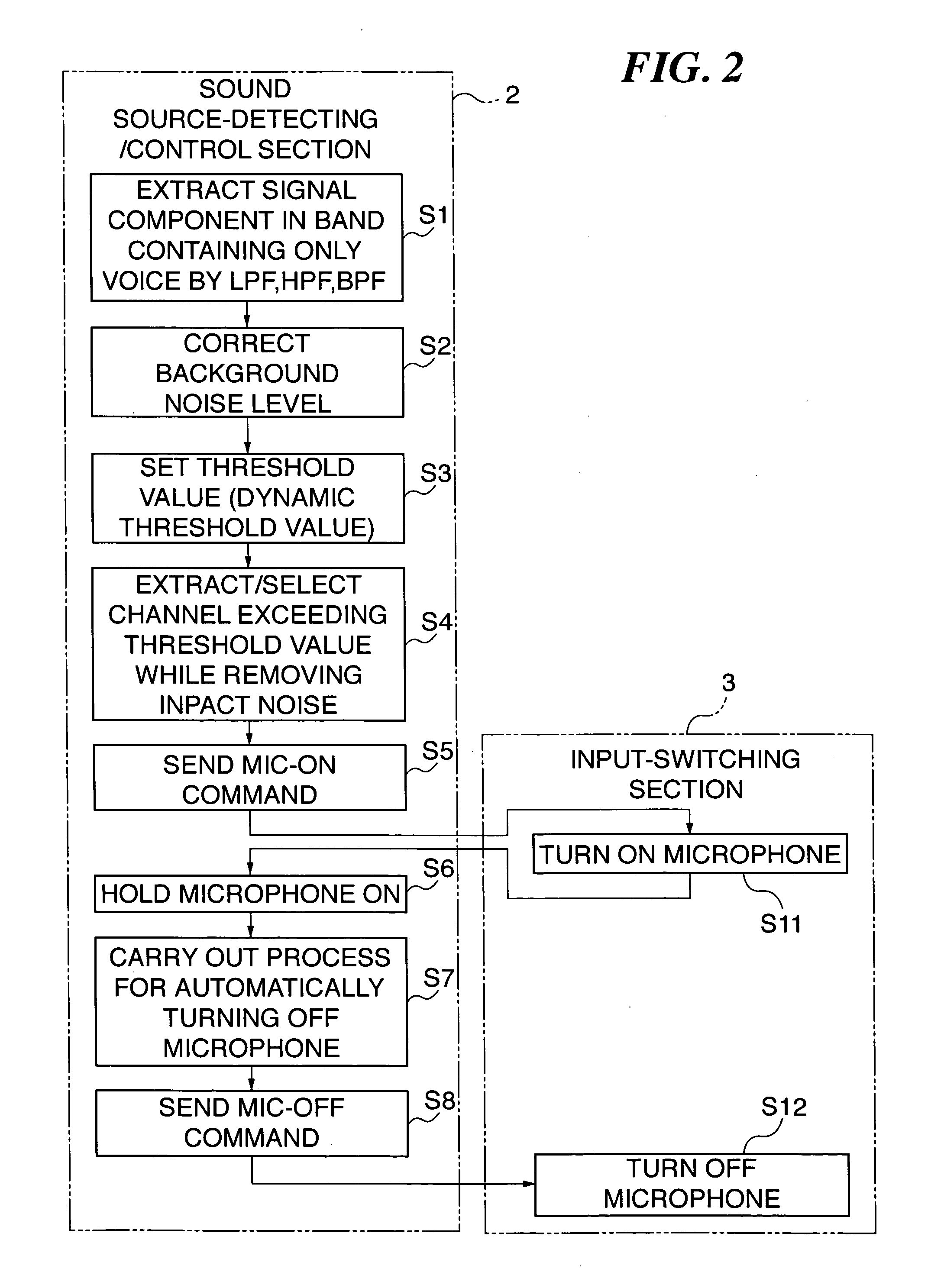
A hands-free loudspeaker system which is capable of achieving high-quality voice amplification without requiring a human speaker to move to a microphone or a microphone to be moved to a human speaker. A microphone whose input level has continued to be above a threshold value for not shorter than a predetermined time period is detected, based on input signals from dispersedly arranged microphones. An input signal from the microphone is selected and outputted to each loudspeaker at an output level or with a delay time, according to a location of the loudspeaker. A preset lowest threshold level is initially set to the threshold value, and an input level of the microphone higher than the threshold value is newly set to the same, while when the input level is lower than the threshold value, a lower value is set to the same in a step-by-step manner.

Description

BACKGROUND OF THE INVENTION [0001] 1. Field of the Invention [0002] The present invention relates to a loudspeaker system. [0003] 2. Description of the Related Art [0004] In the case where a human speaker and an audience are present within the same room having an area or space so large that the human speaker cannot make his / her own voice sufficiently heard by the audience, voice amplification is necessitated. [0005] Conventionally, to carry out voice amplification, a human speaker has to utter voice at a location where a microphone is fixedly set, or otherwise has to carry a microphone, for collection of clear sound. Further, during a question-and-answer session or the like when people present make speeches in turns, each human speaker is required to move to the fixed microphone, or the microphone, not fixed, is required to be moved to the human speaker. [0006] Further, a reproduction system, which is generally comprised of loudspeakers in a centralized arrangement or loudspeakers d...

Claims


Application Information

Patent Timeline
Patent Type & Authority Applications(United States)
IPC IPC(8): H04R5/02
CPCH04S7/303H04R27/00
Inventor ITO, ATSUKOMIKI, AKIRASAWARA, SHINICHI
Owner YAMAHA CORP
Learn More