Visual mapping of field device message routes in a wireless mesh network

a wireless mesh network and message route technology, applied in the field of wireless mesh networks, can solve the problems of high installation cost, high cost involved in running such a long cable, and achieve the effect of improving communication performan

Inactive Publication Date: 2007-07-12
FISHER-ROSEMOUNT SYST INC
View PDF64 Cites 144 Cited by
  • Summary
  • Abstract
  • Description
  • Claims
  • Application Information

AI Technical Summary

Benefits of technology

[0015] Network performance parameters can include, for example, identification of other nodes with which a particular node has established communication links, radio signal strength on each of the links, number of lost messages or other errors on each link, and how often communication occurs on each of the links. The visual representation allows the user to inspect the communication paths within the mesh network to identify potential problems and to make adjustments to the network to improve communication performance.

Problems solved by technology

If the remote application is, for example, a half of a mile away, the costs involved in running such a long cable can be high.
If multiple homerun cables have to be run to the remote application, the costs become even higher.
Power outlets, such as 120 VAC utilities, are typically not located nearby or may not be allowed into the hazardous areas where the instrumentation (sensors) and actuators must be located without incurring great installation expense.
The more descendants a node has, the more traffic it must route, which in turn directly increases its own power consumption and diminishes its battery life.

Method used


Image

  • Visual mapping of field device message routes in a wireless mesh network
  • Visual mapping of field device message routes in a wireless mesh network
  • Visual mapping of field device message routes in a wireless mesh network

Examples


Embodiment Construction

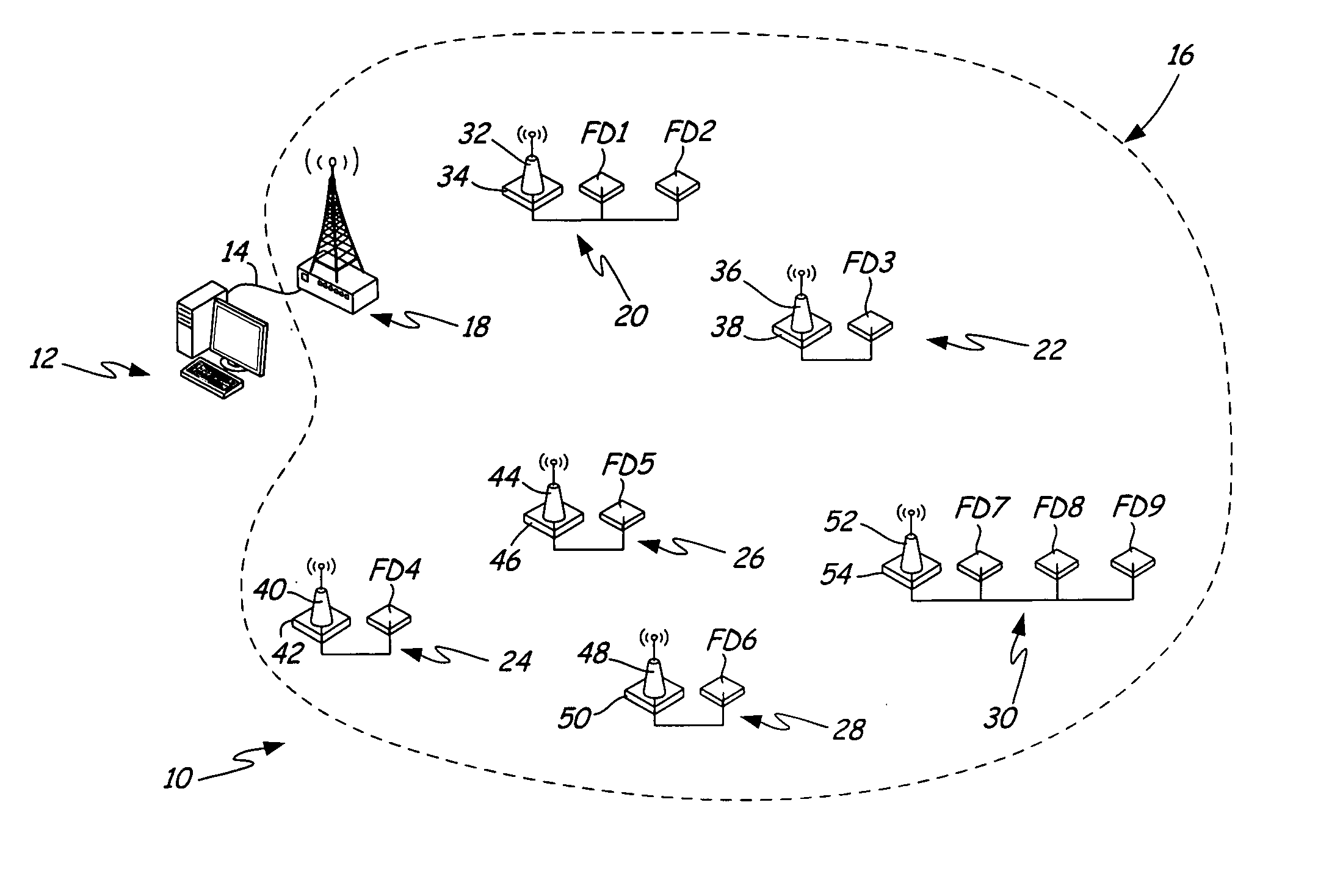
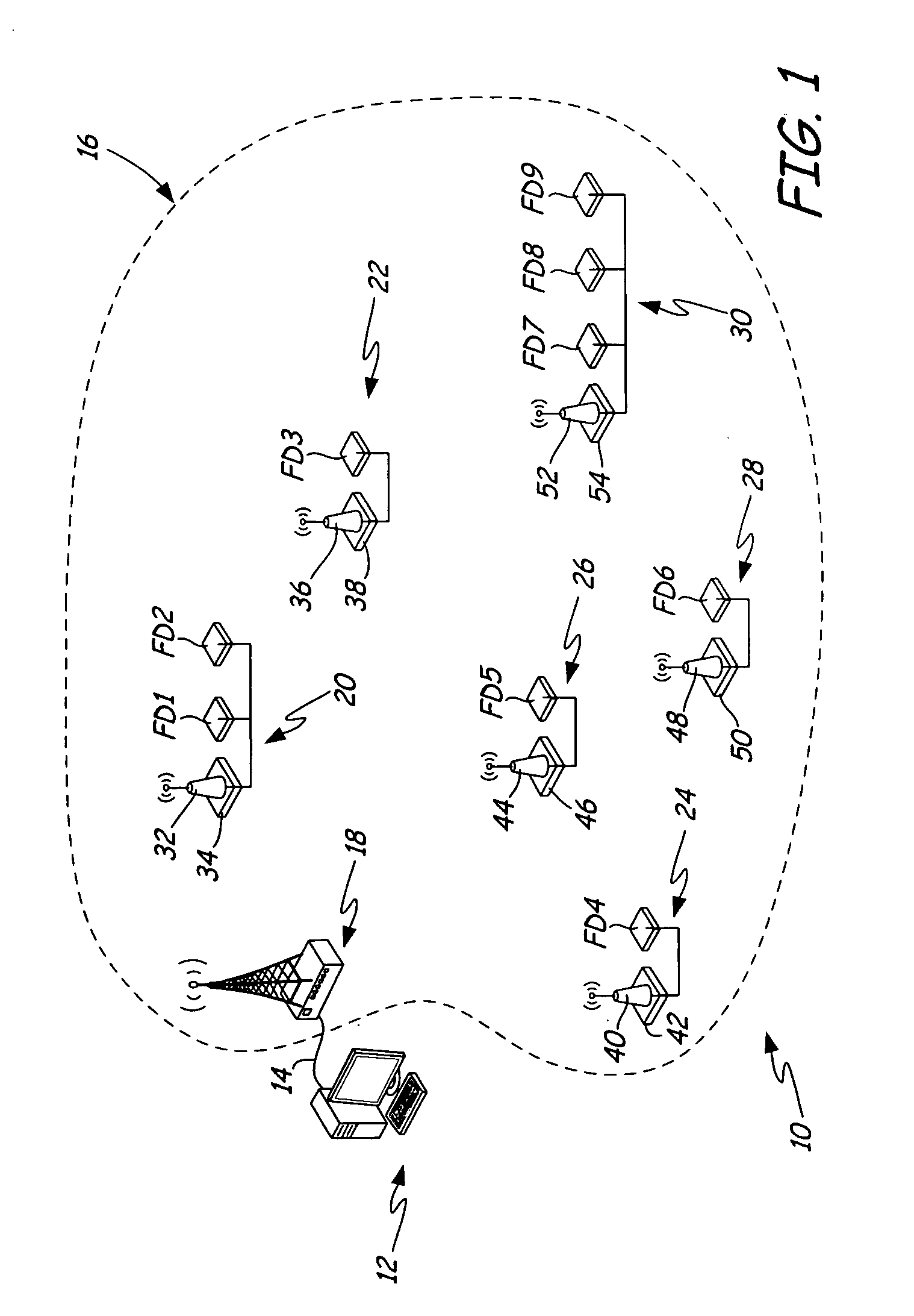
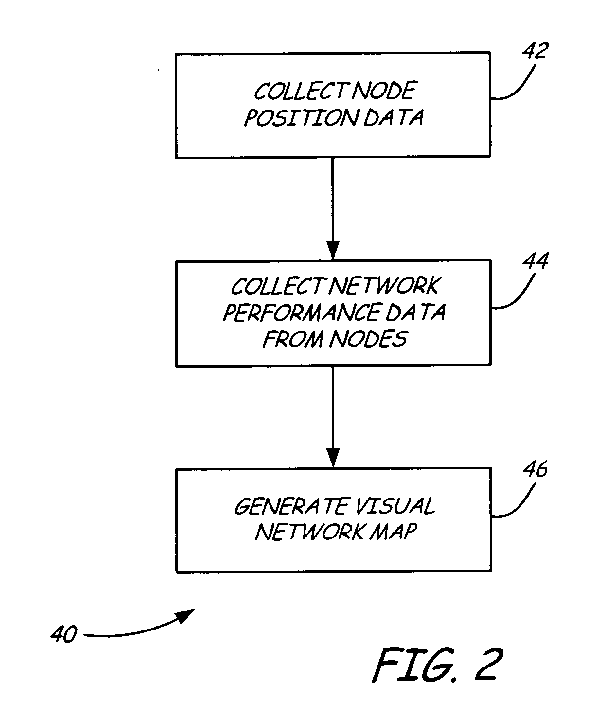
[0020] This invention provides a method for graphically visualizing the route a message takes as it passes between nodes in a wireless mesh network. In a typical control system, a host computer at a control center interacts with field devices located within a physical plant and displays information they have to offer. The communication of messages between the host computer and the field devices can be over wired connections or over a wireless mesh network. In a low power wireless mesh network, a device message does not pass from the host to the target field device directly; it can take a multitude of routes within the wireless mesh network before reaching its destination. In practice, it is desirable to understand the routes messages take through the wireless mesh network so that the topology of the physical network can be adjusted if needed to enable the network to communicate in a more desirable way. Presently there is no way for a qualified person to inspect the dynamic nature of...


PUM


Abstract

A control system uses a wireless mesh network to provide communication between a host computer and field devices. Performance of the wireless mesh network is monitored by collecting network performance data from each node, such as the nodes with which it is communicating, received signal strengths over links to different nodes, the number of errors occurring on each link, and how frequently communication is occurring with each of the other nodes. A visual network map is generated using performance statistics based on the data gathered from the nodes of the wireless mesh network. The visual network map allows a user to determine the routes that messages take through the wireless mesh network, diagnose potential problems, and make adjustments to improve network performance.

Description

CROSS-REFERENCE TO RELATED APPLICATIONS [0001] This application claims priority from a co-pending application entitled LOW POWER WIRELESS NETWORKS OF FIELD DEVICES, Ser. No. 60 / 758,167, filed on Jan. 11, 2006, which is incorporated by reference. [0002] Reference is also made to co-pending applications filed on even date with this application: CONTROL OF FIELD DEVICE ON LOW POWER WIRELESS NETWORKS, Ser. No. ______; CONTROL SYSTEM WITH WIRELESS ADDRESS DOMAIN TO FIELD DEVICE ADDRESS DOMAIN TRANSLATION, Ser. No. ______; CONTROL SYSTEM WITH PREDICTIVE FIELD DEVICE RESPONSE TIME OVER A WIRELESS NETWORK, Ser. No. ______; SELECTIVE ACTIVATION OF FIELD DEVICES IN LOW POWER WIRELESS MESH NETWORKS, Ser. No. ______; CONTROL OF LOW POWER WIRELESS NETWORKS FOR POWER CONSERVATION, Ser. No. ______; and CONTROL SYSTEM WITH WIRELESS MESSAGES CONTAINING MESSAGE SEQUENCE INFORMATION. Ser. No. ______, which are incorporated by reference.BACKGROUND OF THE INVENTION [0003] The present invention relates t...

Claims


Application Information

Patent Timeline
Patent Type & Authority Applications(United States)
IPC IPC(8): H04Q7/20H04L45/24H04L45/28H04W4/18H04W8/26H04W16/18H04W16/22H04W24/08H04W40/00H04W40/10H04W52/02H04W76/04H04W80/00H04W88/16H04W92/00
CPCG05B2219/31162Y02B60/50H04L41/00H04L41/12H04L41/22H04L43/045H04L45/22H04L45/24H04L45/28H04L47/10H04L47/14H04L47/34H04W4/18H04W8/26H04W16/18H04W16/22H04W24/08H04W40/00H04W40/08H04W40/10H04W40/22H04W40/24H04W52/0225H04W56/00H04W76/04H04W80/00H04W84/18H04W88/16H04W92/00H04L12/24H04W76/20H04W52/02H04L47/28H04W52/0229Y02D30/70H04W28/02H04W8/04
Inventor DOBROWSKI, PATRICK M.LOVEGREN, ERIC R.ORTH, KELLY M.STOTZ, KYLE L.
Owner FISHER-ROSEMOUNT SYST INC
Why Eureka
Try Eureka