
Location estimation method

Inactive Publication Date: 2007-07-12
MEDIATEK INC
View PDF27 Cites 16 Cited by
  • Summary
  • Abstract
  • Description
  • Claims
  • Application Information

AI Technical Summary

Problems solved by technology

When the confined region ABC grows as the NLOS error increases, the accuracy of the two-step LS algorithm may significantly decrease, particularly for an MS located at the boundaries of arcs AB, BC and CA.

Method used


Image

  • Location estimation method
  • Location estimation method
  • Location estimation method

Examples


Embodiment Construction

[0023]The following description is of the best-contemplated mode of carrying out the invention. This description is made for the purpose of illustrating the general principles of the invention and should not be taken in a limiting sense. The scope of the invention is best determined by reference to the appended claims.

[0024]According to N. Levanon, “Lowest GDOP in 2-D Scenarios” Published in Navig., vol. 147, June 2002, geometric BS distribution may affect MS estimation accuracy, thus a geometric dilution of precision (GDOP) is defined as a dimensionless expression to describe a ratio between location estimation error and the associated measurement error, such as NLOS or noise in TOA measurement. Typically, higher GDOP indicates worse conditions. The paper explained how to develop a GDOP contour for a given geometric distribution.

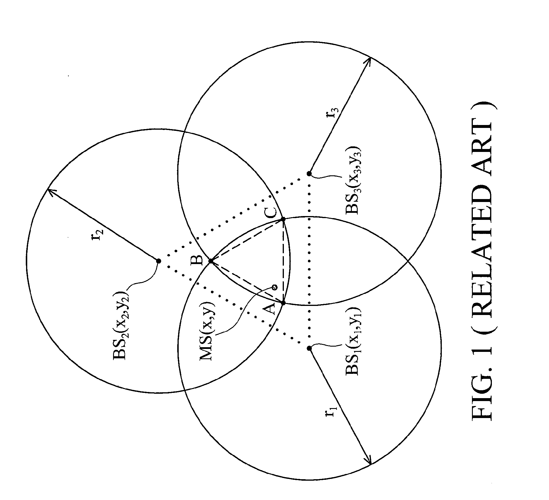
[0025]From the intuitional perspective of FIG. 1, an actual MS location (x,y) is expected to be found within the confined region ABC. By using the conventi...


PUM


Abstract

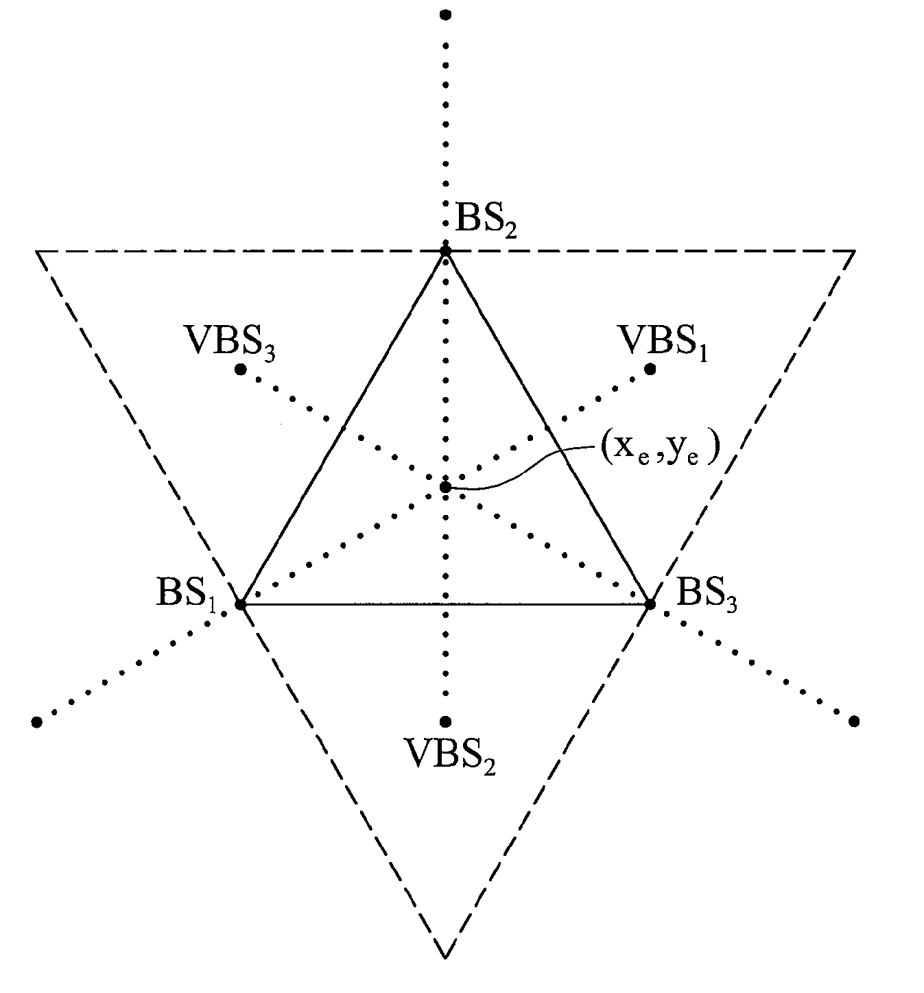
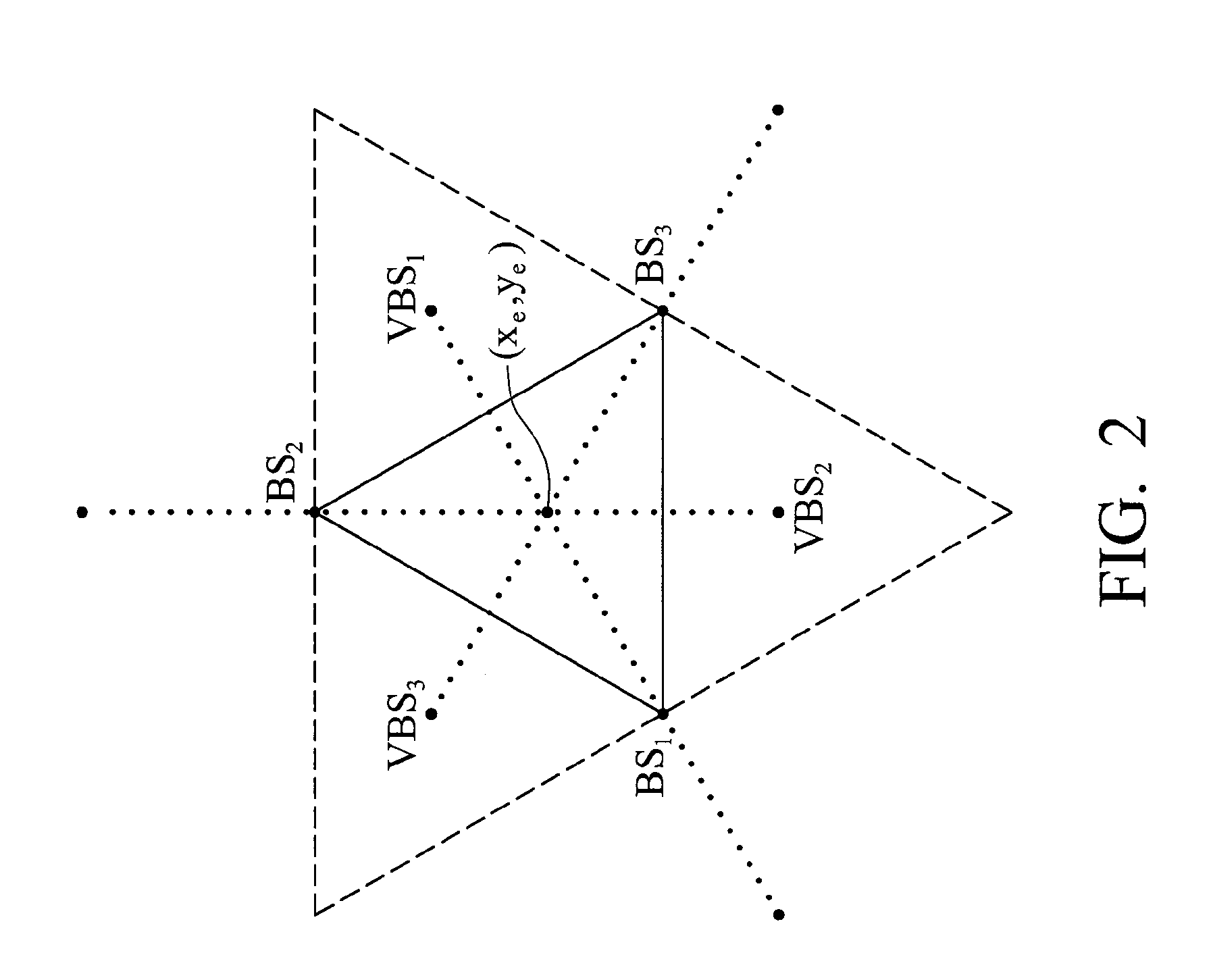
A location estimation method is provided. The method locates coordinates of a mobile station (MS) by referencing a plurality of base stations (BS). A geometric distribution of the BS is analyzed to provide a list of conditional equations. A virtual BS is allocated, having a virtual distance to the MS to provide a constraint equation. The MS location is derived from the conditional equations and the constraint equation.

Description

CROSS REFERENCE TO RELATED APPILCATIONS[0001]This application claims the benefit of U.S. Provisional Application No. 60 / 757,140, filed Jan. 6, 2006.BACKGROUND OF THE INVENTION[0002]1. Field of the Invention[0003]The invention relates to wireless location systems, and more particularly, to enhanced precision in location estimation of a mobile station under different environments.[0004]2. Description of the Related Art[0005]Mobile location estimation is of considerable interest in wireless communications. A mobile station (MS) may locate itself by communicating with a plurality of geometrically distributed base stations (BS).[0006]FIG. 1 shows a Time-of-Arrival (TOA) based location estimation with three base stations. For a lth BS, TOA tl is estimated as:tl=rlc=ζlc+nll=1,2,…,N(1)[0007]Where c is the speed of light, rl represents the measured relative distance between the mobile station (MS) and lth BS, composed of actual distance ζl and TOA measurement noise nl. The actual distance ζl...

Claims


Application Information

Patent Timeline
IPC IPC(8): H04Q7/20H04W64/00
CPCH04W64/00
Inventor CHEN, CHAO-LINFENG, KAI-TEN
Owner MEDIATEK INC
Learn More