Intervertebral disc prosthesis and instrumentation for insertion of the prosthesis between the vertebrae

a technology for intervertebral discs and instruments, applied in the field of intervertebral disc prosthesis, can solve the problems of difficult inserting between the vertebrae, lack of stability, and inability to generally ensure the stability of the elements

Active Publication Date: 2007-07-12
LDR MEDICAL
View PDF99 Cites 175 Cited by
  • Summary
  • Abstract
  • Description
  • Claims
  • Application Information

AI Technical Summary

Benefits of technology

[0005] In this context, it is interesting to propose a prosthesis and associated instrumentation enabling the prosthesis to be implanted between the vertebrae, while retaining the necessary alignment of the different elements of the prosthesis between one another. The aim of the present invention therefore is to eliminate certain disadvantages of the prior art by proposing an intervertebral disc prosthesis and instrumentation for insertion of the prosthesis between the vertebrae allowing the prosthesis to be implanted by following a defined axis.

Problems solved by technology

However, the disadvantage of these prostheses is that they are not easy to insert between the vertebrae, since implantation requires good stability of the different elements of the prosthesis between one another.
This stability is often missing in prostheses known from the prior art and the known instrumentation does not generally ensure stability of the elements of the prosthesis.
In fact, the articulated plates of the prostheses possess degrees of liberty conferring comfort to the patient, but discomfort for the surgeon who fits them.
The surgeon is therefore not guaranteed that the elements are properly aligned in the antero-posterior axis of the vertebral column.

Method used


Image

  • Intervertebral disc prosthesis and instrumentation for insertion of the prosthesis between the vertebrae
  • Intervertebral disc prosthesis and instrumentation for insertion of the prosthesis between the vertebrae
  • Intervertebral disc prosthesis and instrumentation for insertion of the prosthesis between the vertebrae

Examples


Embodiment Construction

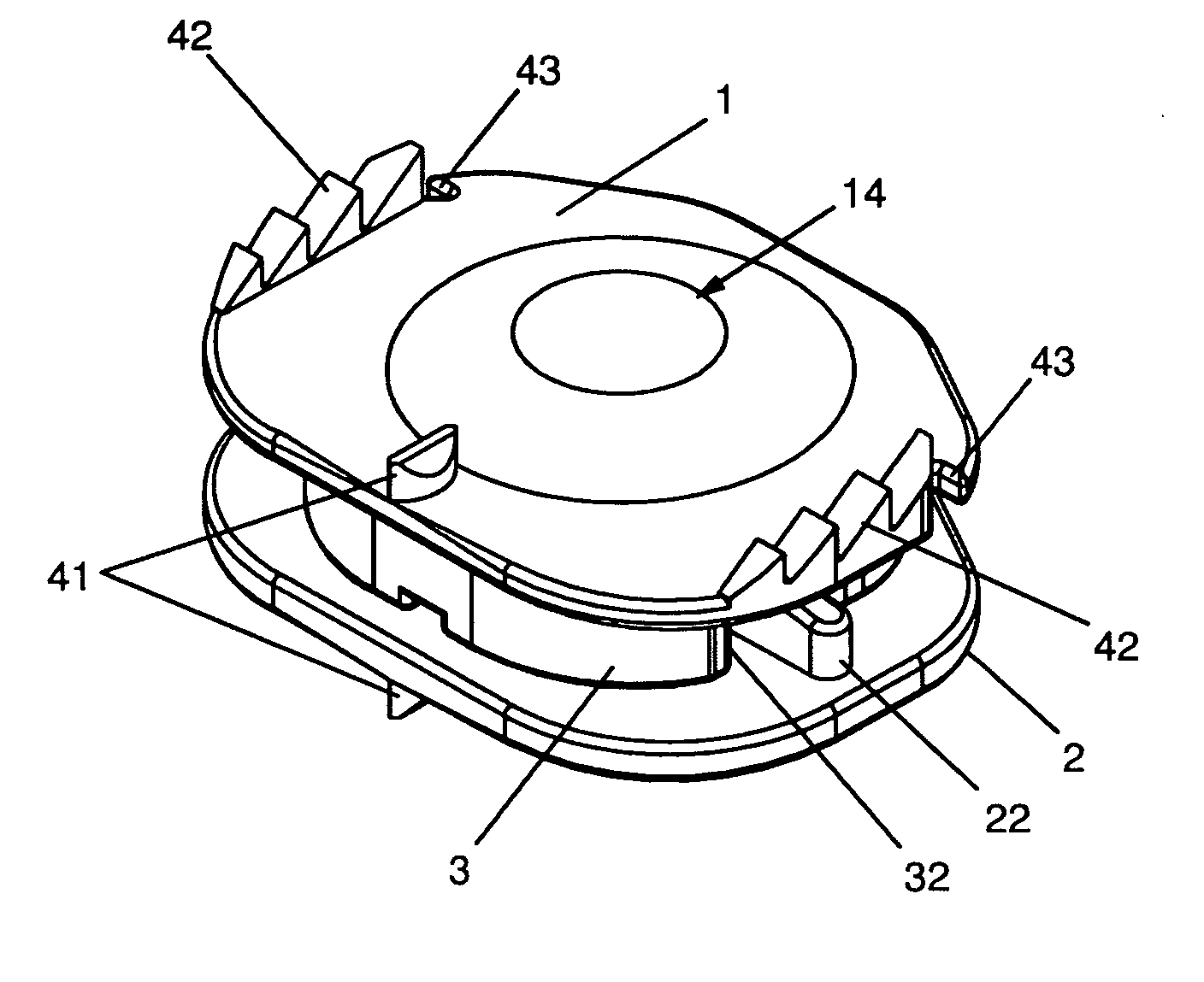
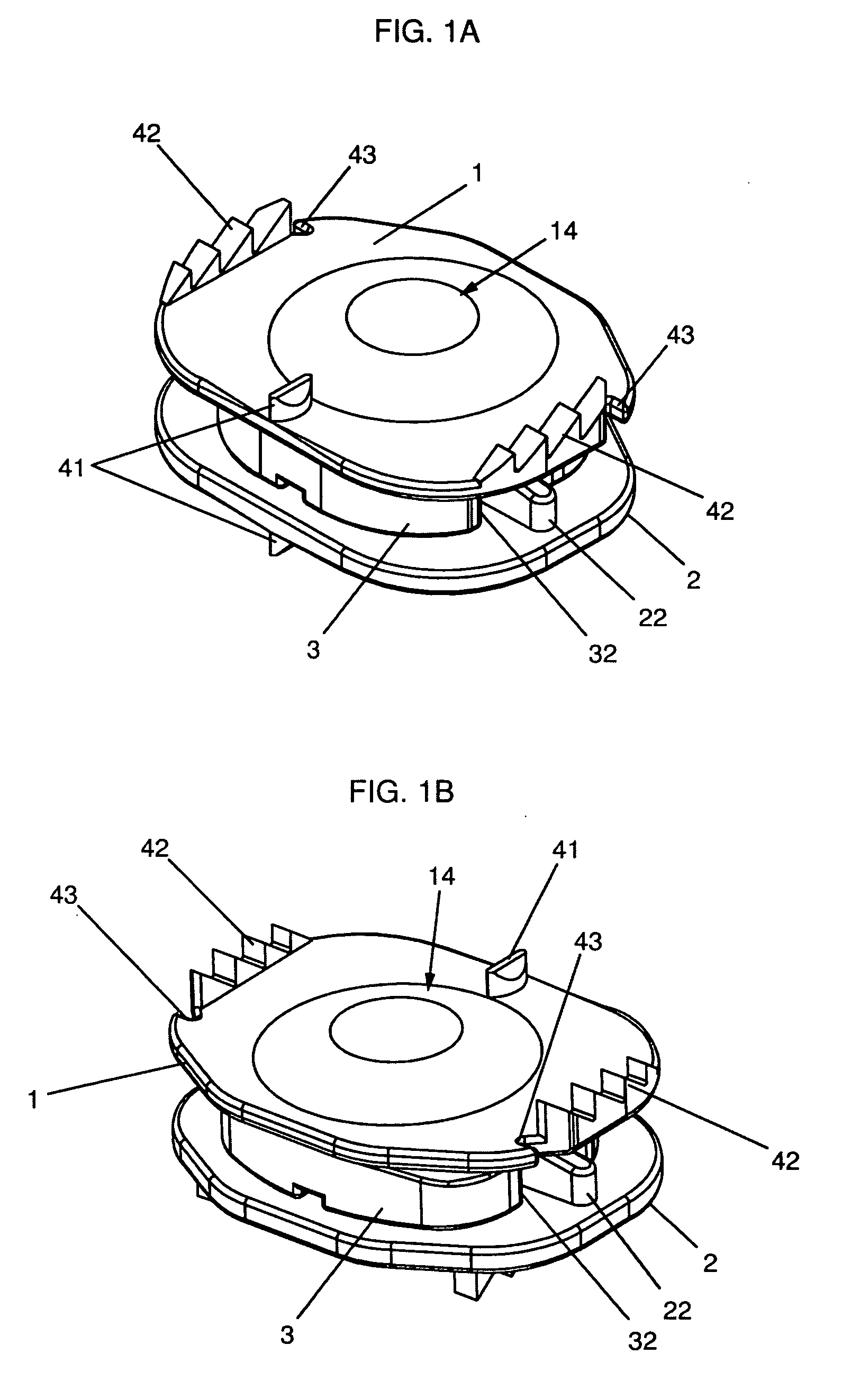
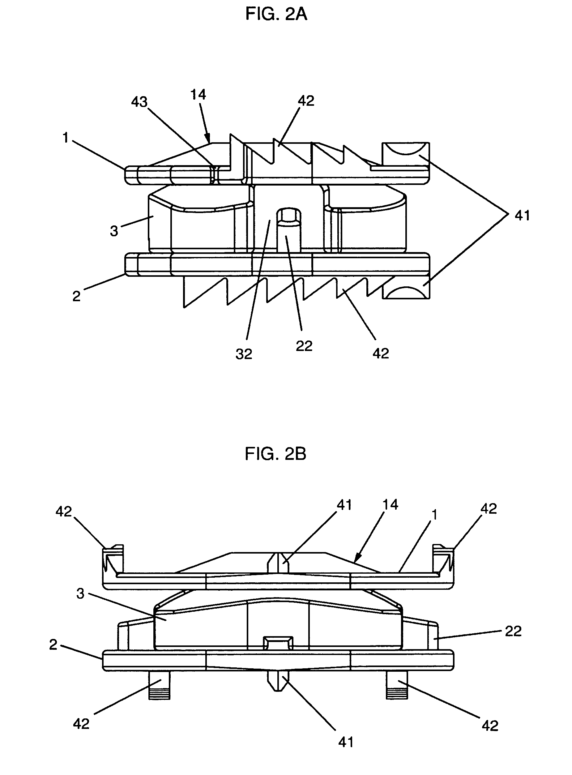
[0047] The present invention relates to an intervertebral disc prosthesis comprising at least osseous anchoring means (41) forming a guide blade intended to prevent rotation of the plates of the prosthesis between one another and facilitate insertion of the prosthesis. More precisely, the prosthesis comprises at least first osseous anchoring means (42) and at least second osseous anchoring means (41), the first osseous anchoring means (42) extending to near the periphery of the plate on which it is situated and the second osseous anchoring means (41) being offset according to the antero-posterior axis relative to the first osseous anchoring means (42). The second offset osseous anchoring means (41) comprise a portion, so-called basal, solid with the plate on which it is situated and a portion, so-called sharp-edged, of width narrower than the basal portion. This sharp-edged portion forms a sort of blade intended to score the surfaces of the vertebral plates with which it comes into ...


PUM


Abstract

The present invention relates to an intervertebral disc prosthesis and insertion instrumentation, the prosthesis comprising at least first and second osseous anchoring means, the first osseous anchoring means disposed proximal to the periphery of the plate on which it is situated and the second osseous anchoring means being offset along the antero-posterior axis, the second osseous anchoring means comprising a basal portion and a sharp-edged portion of width narrower than the basal portion. The instrumentation comprises a rod fitted with at least two feet forming a clip and sliding in a tube, sliding the rod in the tube, in the direction of the manipulation end, causing closing of the clip by contact between the exterior of the feet and a truncated portion of the tube and sliding the rod in the tube, in the direction of the prehension end, causing opening of the clip by contact between an axis and the interior of the feet of the rod.

Description

CROSS REFERENCE TO RELATED APPLICATIONS [0001] This application claims priority under 35 U.S.C. 119 to French Patent Application No. 05 12133, filed in FRANCE on Nov. 30, 2005. BACKGROUND OF THE INVENTION [0002] The present invention concerns an intervertebral disc prosthesis, intended to be substituted for fibro-cartilaginous discs ensuring connection between the vertebrae of the spinal column. [0003] Various types of intervertebral disc prostheses are known in the prior art. Numerous prostheses, such as for example in the patent applications WO 02 089 701 and WO 2004 / 041129, are constituted by a lower plate and an upper plate forming a sort of cage articulated about a central core. Other prostheses such as those described in the patent U.S. Pat. No. 5,676,701 and in the patent application WO 03 / 059212 A1, for example, comprise only a lower plate and an upper plate articulated to one another by means of an articulation surface. The advantage of these two types of articulated prosth...

Claims


Application Information

Patent Timeline
Patent Type & Authority Applications(United States)
IPC IPC(8): A61F2/44
CPCA61F2/4425Y10S606/914A61F2002/30235A61F2002/30365A61F2002/30369A61F2002/30512A61F2002/30601A61F2002/30616A61F2002/30649A61F2002/30662A61F2002/30841A61F2002/30878A61F2002/30884A61F2002/30904A61F2002/443A61F2002/4622A61F2002/4627A61F2002/4628A61F2220/0025A61F2220/0033A61F2230/0069A61F2/4611A61F2002/30507A61F2/44A61F2/46A61F2002/30593
Inventor RASHBAUM, RALPHKIM, KEE D.BAE, HYUNSTEIB, JEAN-PAUL
Owner LDR MEDICAL
Why Eureka
Try Eureka