
Reagent refill and supply system for an SCR exhaust aftertreatment system

a technology of exhaust aftertreatment and supply system, which is applied in the direction of engines, mechanical equipment, machines/engines, etc., can solve the problems of logistics difficulties in supply solutions, and achieve the effect of quick and easy replenishmen

Inactive Publication Date: 2007-07-19
CUMMINS INC
View PDF5 Cites 43 Cited by
  • Summary
  • Abstract
  • Description
  • Claims
  • Application Information

AI Technical Summary

Benefits of technology

[0012] An advantage of the present invention is that the reagent can be quickly and easily replenished in a motor vehicle at periodic intervals as it is depleted from the reagent holding tank.
[0013] Another advantage is that the periodic interval can be a predetermined interval or can be a varying interval based upon a sensed reagent level in the holding tank.
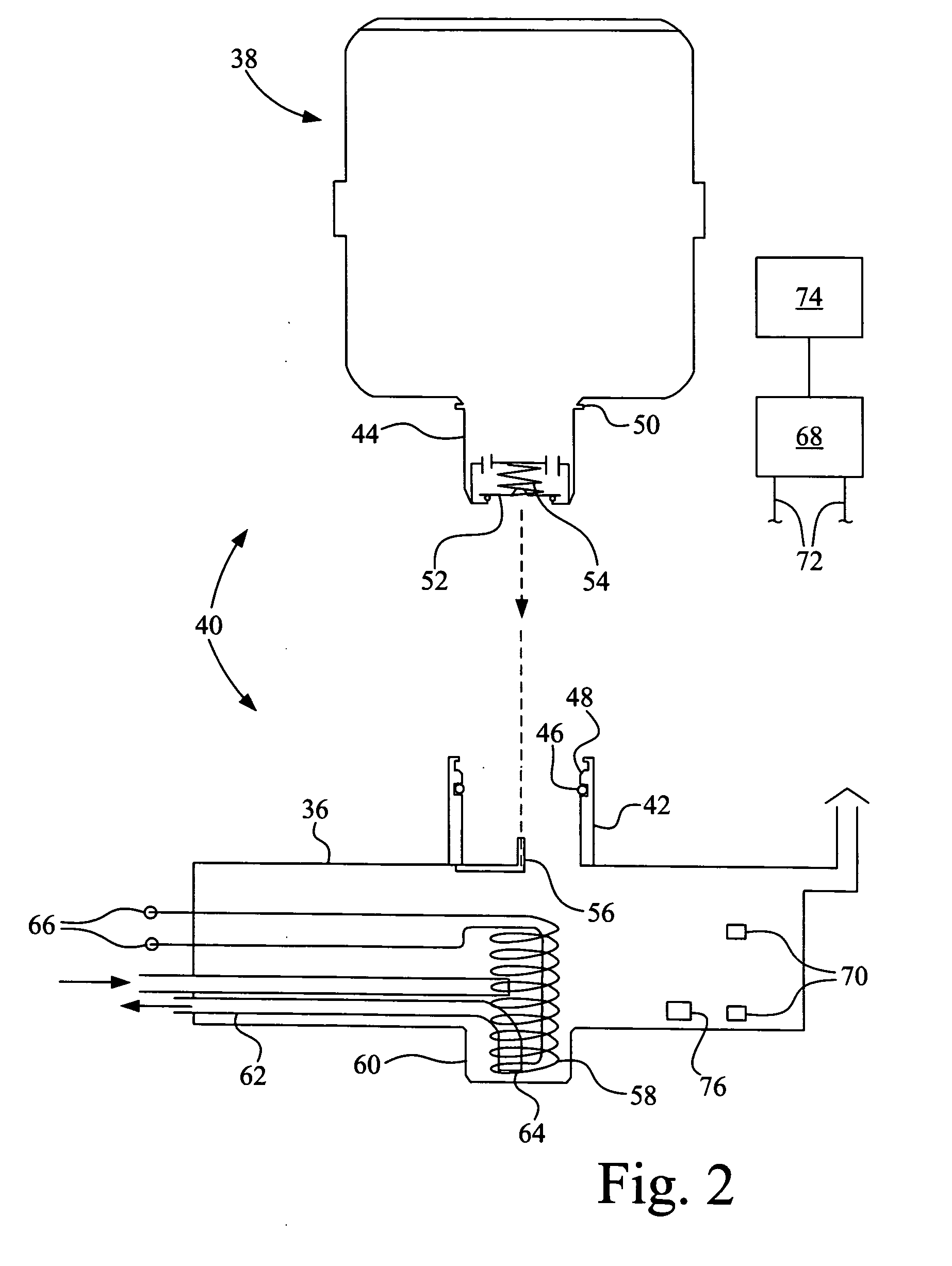
[0014] Yet another advantage is that the reagent supply canister is sealed to the ambient environment and automatically opened upon coupling with the reagent holding tank to allow reagent refilling.

Problems solved by technology

This urea mixture supply solution may have logistics difficulties, however, with inadvertent spillage from the nozzle, the need to dedicate or retrofit a supply hose and nozzle at each fueling island, etc.

Method used


Image

  • Reagent refill and supply system for an SCR exhaust aftertreatment system
  • Reagent refill and supply system for an SCR exhaust aftertreatment system
  • Reagent refill and supply system for an SCR exhaust aftertreatment system

Examples


Embodiment Construction

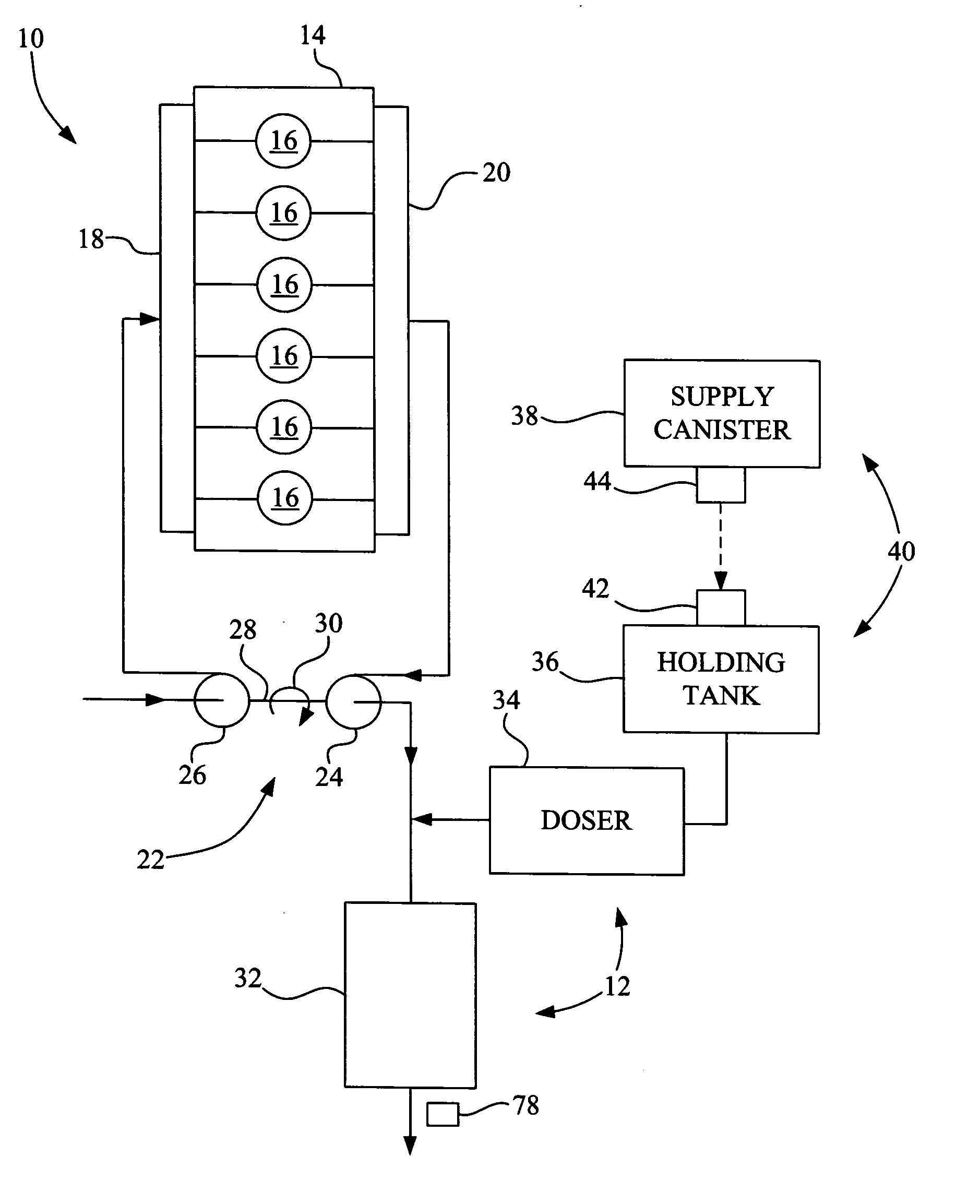
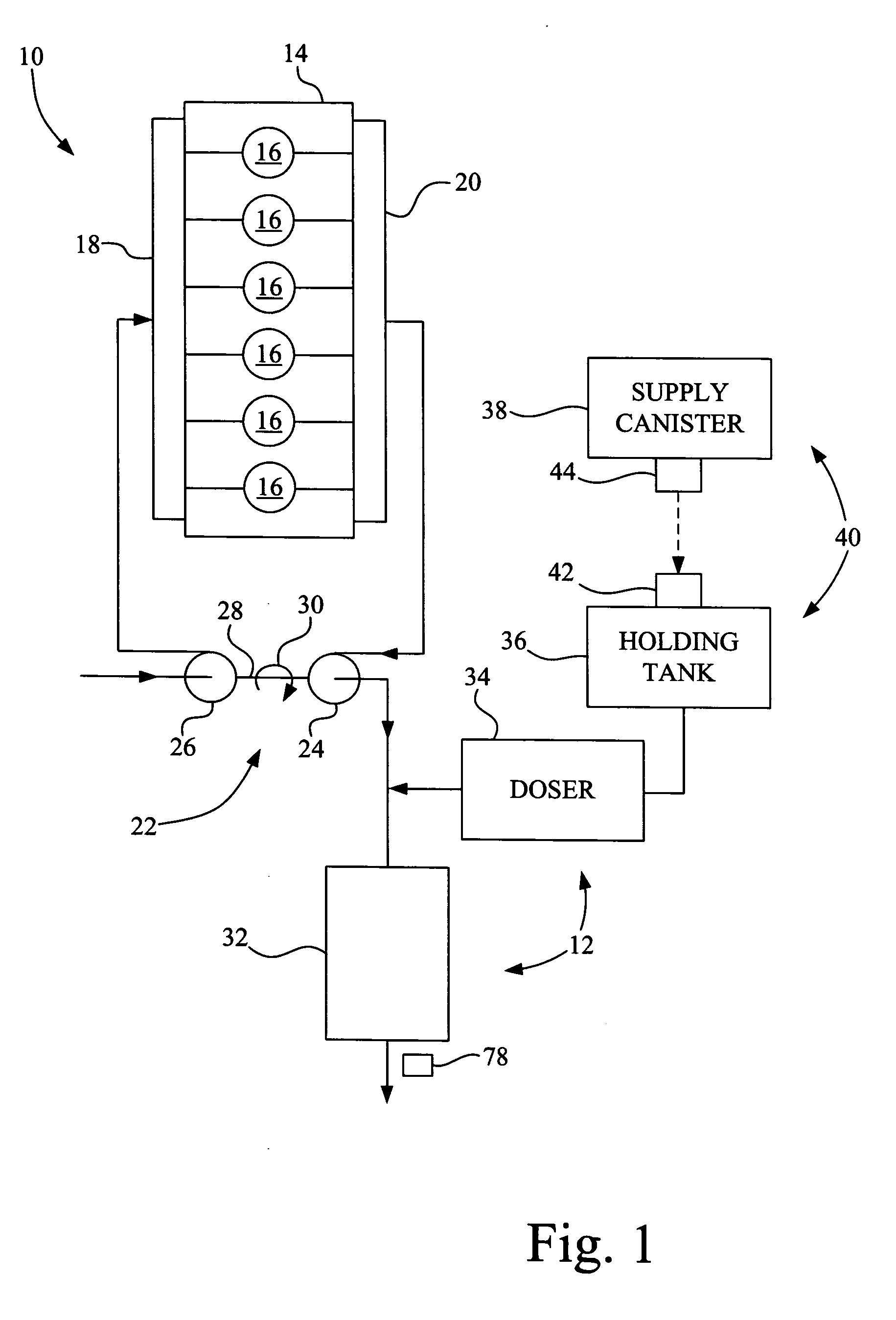
[0021] Referring now to the drawings, and more particularly to FIG. 1, there is shown an IC engine 10 including an embodiment of an SCR exhaust aftertreatment 12. In the embodiment shown, IC engine 10 is a diesel engine including a cylinder block 14 defining a plurality of combustion cylinders 16, an intake manifold 18, an exhaust manifold 20 and a turbocharger 22.

[0022] Cylinder block 14 is shown as including six combustion cylinders, but may also include a different number of combustion cylinders, such as eight, ten or twelve combustion cylinders.

[0023] Intake manifold 18 and exhaust manifold 20 are each in fluid communication with the plurality of combustion cylinders 16, and may be of single part design, as shown, or of multiple part design.

[0024] Exhaust manifold 20 discharges exhaust gas to turbine 24 of turbocharger 22. Turbine 24 may be of a fixed geometry as shown, or may be an adjustable turbine such as a variable geometry turbine (VGT). Exhaust gas from exhaust manifol...


PUM


Abstract

An internal combustion engine includes an exhaust manifold, and a selective catalytic reduction exhaust aftertreatment system. The selective catalytic reduction exhaust aftertreatment system includes a reduction catalytic converter in communication with the exhaust manifold; a reagent holding tank in fluid communication with the reduction catalytic converter; and a reagent supply canister selectively and removably couplable with the reagent holding tank.

Description

BACKGROUND OF THE INVENTION [0001] 1. Field of the Invention [0002] The present invention relates to exhaust aftertreatment systems for use in internal combustion engines, and, more particularly, to such exhaust aftertreatment systems using selective catalytic reduction. [0003] 2. Description of the Related Art [0004] Increasingly stringent emissions control standards necessitate continually improved emissions from internal combustion (IC) engines used as motive power for vehicles. At present, the most significant of these emissions are sulfur dioxide (SO2), oxides of nitrogen (NOx), and airborne particulate. [0005] NOx refers to the cumulative emissions of nitric oxide (NO), nitrogen dioxide (NO2) and trace quantities of other species generated during combustion. NOx emissions are minimized using low NOx combustion technology and postcombustion techniques. If combustion modifications alone are insufficient, postcombustion techniques such as selective catalytic reduction (SCR) syste...

Claims


Application Information

Patent Timeline
IPC IPC(8): F01N3/00F01N3/10
CPCF01N3/2066F01N2610/02Y02T10/24F01N2610/14F01N2610/1406F01N2610/10Y02T10/12
Inventor SHERIDAN, TODD A.TIKK, LASZLO D.RADOVANOVIC, ROD
Owner CUMMINS INC
Learn More