

Variable valve actuation mechanism for an internal combustion engine
- Summary
- Abstract
- Description
- Claims
- Application Information
AI Technical Summary
Benefits of technology
Problems solved by technology
Method used
Image

Examples
first embodiment
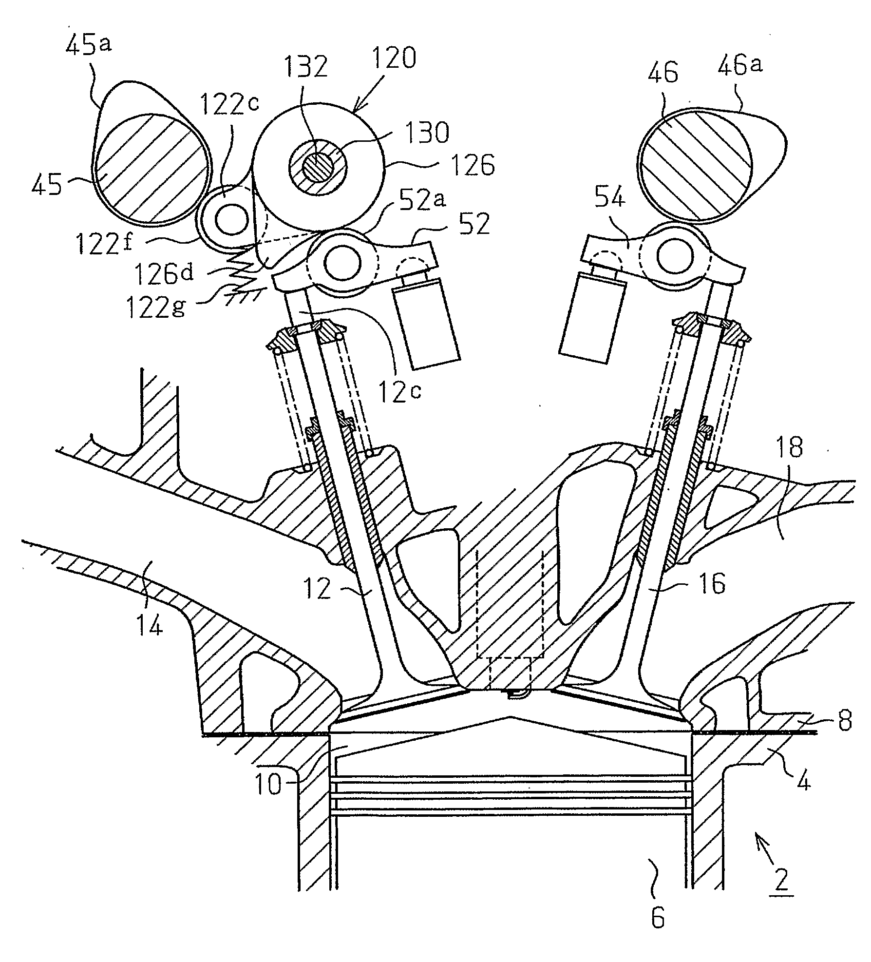
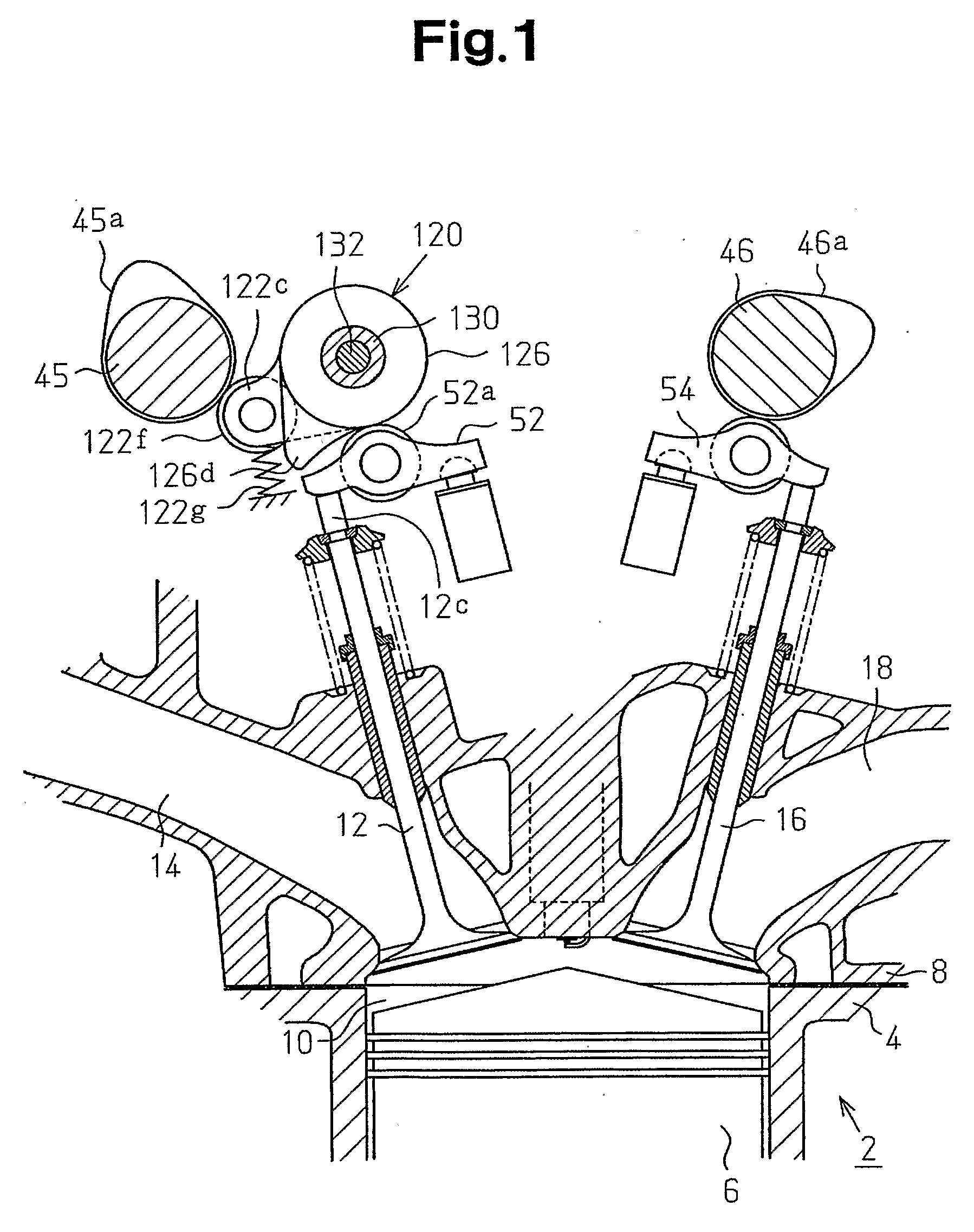
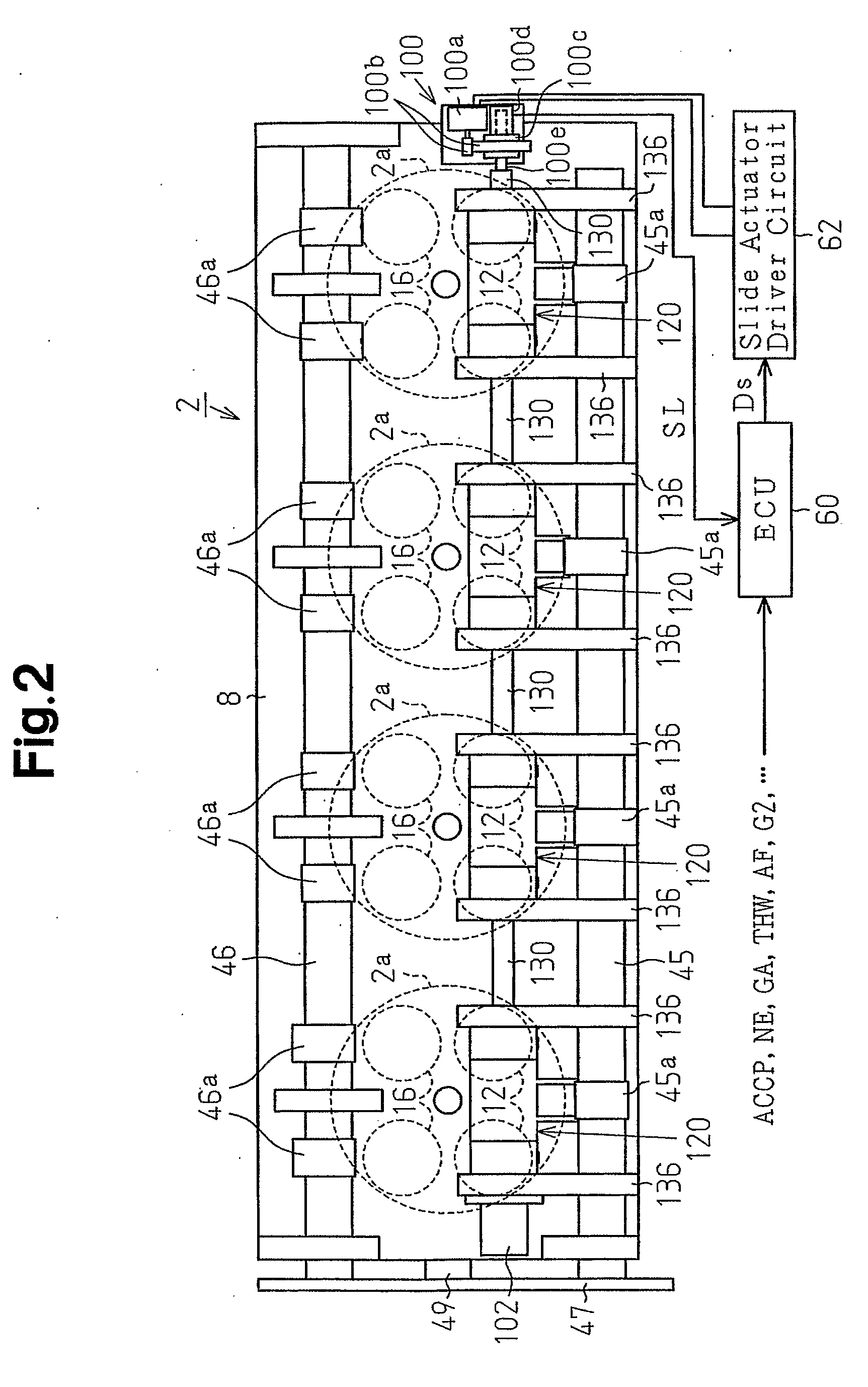
[0088]FIG. 1 illustrates the configuration of a variable valve actuation mechanism of an internal combustion engine, which is a gasoline engine 2 (hereinafter, simply referred to as an engine) in this embodiment. FIG. 1 is a vertical cross-sectional view at a cylinder. FIG. 2 is a plan view that mainly shows the upper portion of the engine 2.
[0089] The engine 2 is mounted on a vehicle to drive the vehicle. The engine 2 has a cylinder block 4, pistons 6, and a cylinder head 8 placed on the cylinder block 4. The cylinder block 4, the pistons 6, and the cylinder head 8 of the engine 2 are made of a light alloy material, which is an aluminum alloy material.
[0090] The cylinder block 4 has cylinders 2a, the number of which is four in this embodiment. In each cylinder 2a, a combustion chamber 10 is defined by the cylinder block 4, the associated piston 6, and the cylinder head 8. Two intake valves 12 and two exhaust valves 16 are provided in each combustion chamber 10. The intake valves ...
second embodiment
[0144] A control shaft 232 of the second embodiment has four engaging portions 232c-1 to 232c-4 and four coupler shafts 232d-1 to 232d-4. The coupler shafts 232d-1 to 232d-4 are made of a material having a thermal expansion coefficient that is greater than that of the cylinder head 8. The coupler shafts 232d-1 to 232d-4 are used with the engaging portions 232c-1 to 232c-4, which are made of an iron based material, such that the thermal expansion coefficient of the entire control shaft 232 is substantially equal to that of the cylinder head 8. Control pins 232a-1 to 232a-4 are made of an iron-based material. The other components are the same as those in the first embodiment, and are thus given the same reference numerals as the first embodiment.
[0145] The engaging portions 232c-1 to 232c-4 are made of an iron-based material the linear expansion coefficient of which is represented by a (1 / ° C.). The coupler shafts 232d-1 to 232d-4 are made of an aluminum alloy material the linear exp...
third embodiment
[0177] In a third embodiment, a control shaft 282 includes a single shaft main body 282d as shown in FIG. 18(A). The shaft main body 282d is made of the same material as that of the cylinder head or of an aluminum alloy material the thermal expansion coefficient is substantially the same as that of the material of the cylinder head.
[0178] As shown in FIG. 18(B), the shaft main body 282d has rectangular holes 282e, the number of which is the same as the number of the cylinders. Each rectangular hole 282e extends in the axial direction. An engaging portion 282c, the shape of which is substantially the same as the rectangular holes 282e, is fitted in each rectangular hole 282e.
[0179] A support hole 282b is formed in each engaging portion 282c. As shown in FIG. 19, the proximal end of a control pin 282a is inserted into and supported by each support hole 282b. The engaging portions 282c and the control pins 282a are both made of a high-strength iron based material.
[0180] The control ...
PUM
 Abstract
Description
Claims
Application Information