Image processing system adapted to eliminate a difference between stored image data and image data to be printed
Inactive Publication Date: 2014-04-22
OKI DATA CORP
View PDF6 Cites 0 Cited by
Summary
Abstract
Description
Claims
Application Information
AI Technical Summary
This helps you quickly interpret patents by identifying the three key elements:
Problems solved by technology
Method used
Benefits of technology
Benefits of technology
The invention provides an image processing system that can print on image data without erasing the printed image. The system includes a judging section that determines if a saving has been performed, a print execution judging section that determines if to print or not, and an image forming section that creates the final printed image based on the print execution judging section's determination.
Problems solved by technology
However, in the former image process system, for example, after image data has been once saved in the storage section, when a print of the image data is performed just after the edit by taking out the image data from the storage section, it can be occurred that the edit operation is made to be completed without saving the edited image data in the storage section by user's mistake.
As a result, there is a problem that the image data that has been edited and printed is erased and difference occurs between the printed image and the content of the un-edited image data that is saved in the PC.
Method used
Image
Click on the blue label to locate the original text in one second.
Reading with bidirectional positioning of images and text.
Examples
embodiment 1
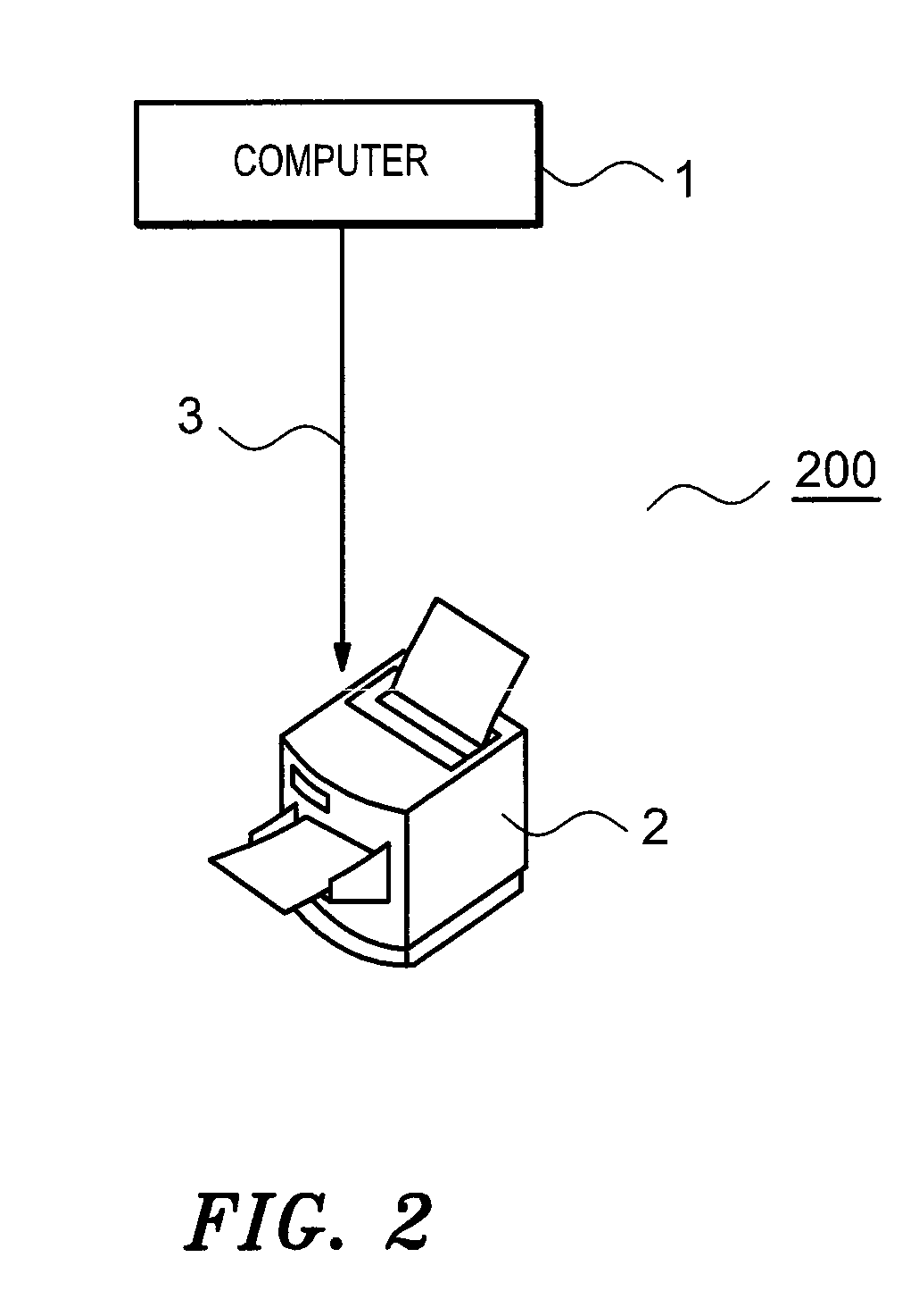
[0032]FIG. 2 is a block diagram showing a foundation structure of an image process system of
[0033]The image process system 200, as shown by FIG. 2, has a PC 1 and a printer 2 that is connected with the PC 1 through a network 3 such as a LAN and the like. By operating the PC 1 through user, the system is operated on the basis of the system program, and it is possible to perform a making, an editing and a print of image data according to respective application programs.
[0034]After user designates a print of image data, according to printer driver program, the image data that should be printed is sent to the printer 2 through the network and is printed.
[0035]The PC 1, as shown by a block diagram of hardware of FIG. 3, comprises a center processing unit (hereinafter: CPU) 101, a ROM 102, a RAM 103 and a hard disc 104 those are storing mediums connected with the CPU 101 through an address / data bus 100, an inputting section 106 that is composed of keyboard and the like connected to the ad...
embodiment 2
[0155]Next, it is to explain operation of the image process system 300 of
[0156]The electric source of the PC 1 and the printer 2 of the image process system 300 is previously set to ON.
[0157]User, in the case to make and print image data, makes image data through the inputting section 106 such as keyboard or mouse and the like, and in the case to print the image data on the paper medium, respective parts of apparatus operate as stated later.
[0158]Firstly, it is to explain about operation of the PC 1 by following the flow chart of FIG. 14 in the case that user tries to execute the print of image data of the present process object under the operation of the application monitoring section 2000.
[0159](S1401)
[0160]According to the print control of the CPU 101, the operation detecting section 21 of the application monitoring section 2000 detects from the document process application 10 that the instruction of the “print execution” process is performed with respect to image data of the pre...
PUM
Abstract
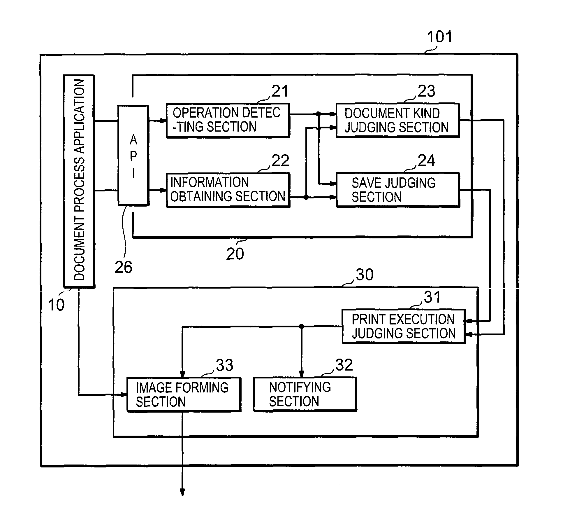
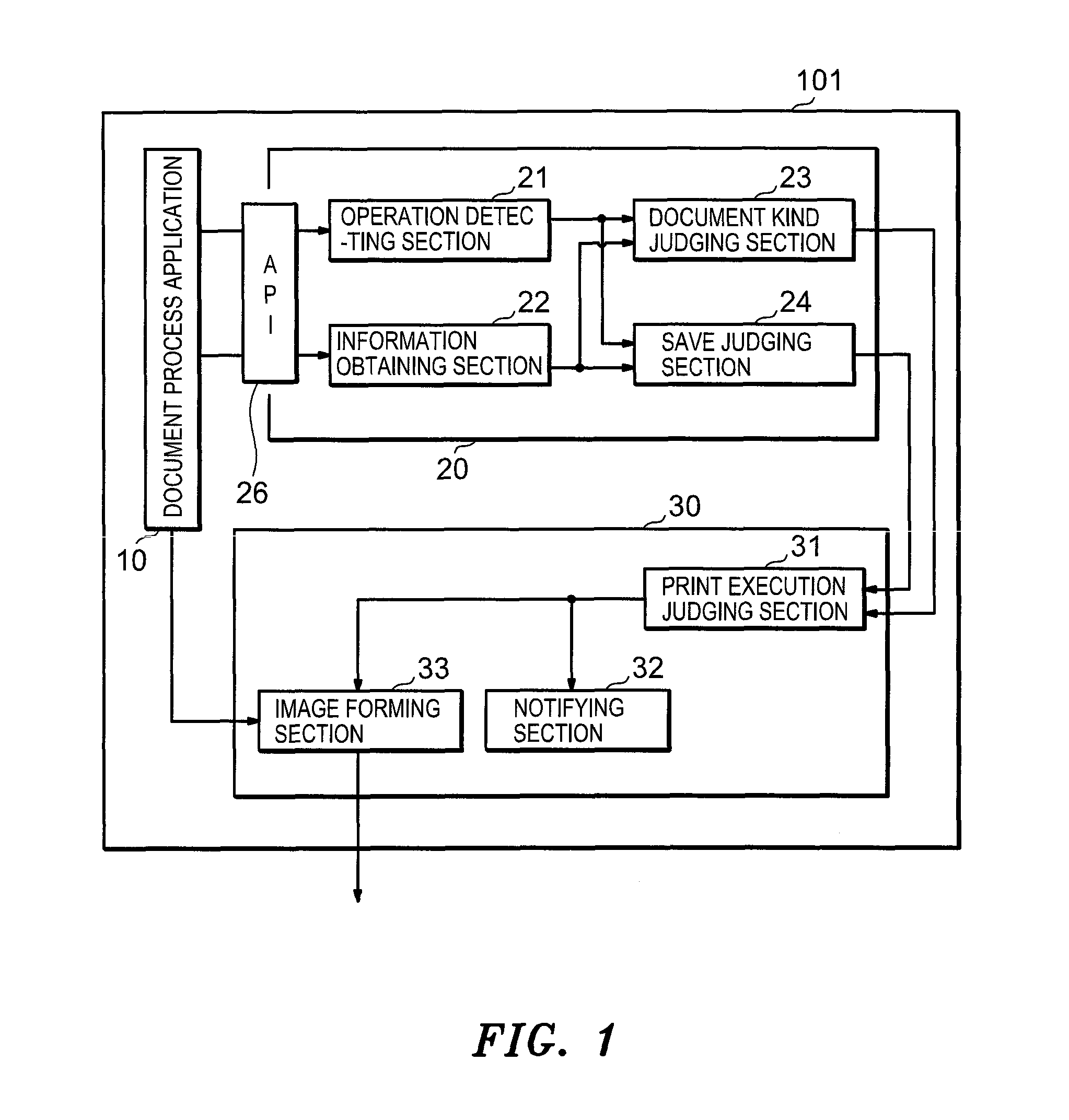
A image process system is supplied that comprises a printer 2 capable of printing on the basis of image data outputted through a personal computer (PC) 1 and the like, wherein the PC 1 comprises a judging section 24 that judges whether or not a saving before the print of the image data has been performed; a print execution judging section 31 that judges whether or not to perform the print of the image data on the basis of the judgment result through the judging section 24; and an image forming section 33 that forms image of the image data capable of being printed on the basis of the judgment result of the print execution judging section 31.
Description
FIELD OF THE INVENTION[0001]The invention relates to an image process system that forms image through a printer and the like on the basis of image data from an image process apparatus such as a personal computer (hereinafter: PC) and the like.BACKGROUND OF THE INVENTION[0002]The image process system has a series of functions such as document making, saving and print, and also has an edit function so as to appropriately perform amendment and deletion of document as need arises from user.[0003]Thus, it is possible for user to save image data in the storage section on the way of making the image data, and after the image data is made, irrespective of print, it is possible for user to make similar image data by using the image data and to make a revised version of the original image data.[0004]The technology that relates to such edit function is disclosed, for example, in the following patent document 1.[0005]The image process system has an input means that inputs image data and the lik...
Claims
Application Information
Patent Timeline
Application Date:The date an application was filed.
Publication Date:The date a patent or application was officially published.
First Publication Date:The earliest publication date of a patent with the same application number.
Issue Date:Publication date of the patent grant document.
PCT Entry Date:The Entry date of PCT National Phase.
Estimated Expiry Date:The statutory expiry date of a patent right according to the Patent Law, and it is the longest term of protection that the patent right can achieve without the termination of the patent right due to other reasons(Term extension factor has been taken into account ).
Invalid Date:Actual expiry date is based on effective date or publication date of legal transaction data of invalid patent.


