

Etch chamber
a technology of etching chamber and etching plate, which is applied in the direction of electrical equipment, decorative surface effects, decorative arts, etc., can solve the problem of reducing the performance of etching chamber, and achieve the effect of reducing the backflow of particles
- Summary
- Abstract
- Description
- Claims
- Application Information
AI Technical Summary
Benefits of technology
Problems solved by technology
Method used
Image

Examples
first embodiment
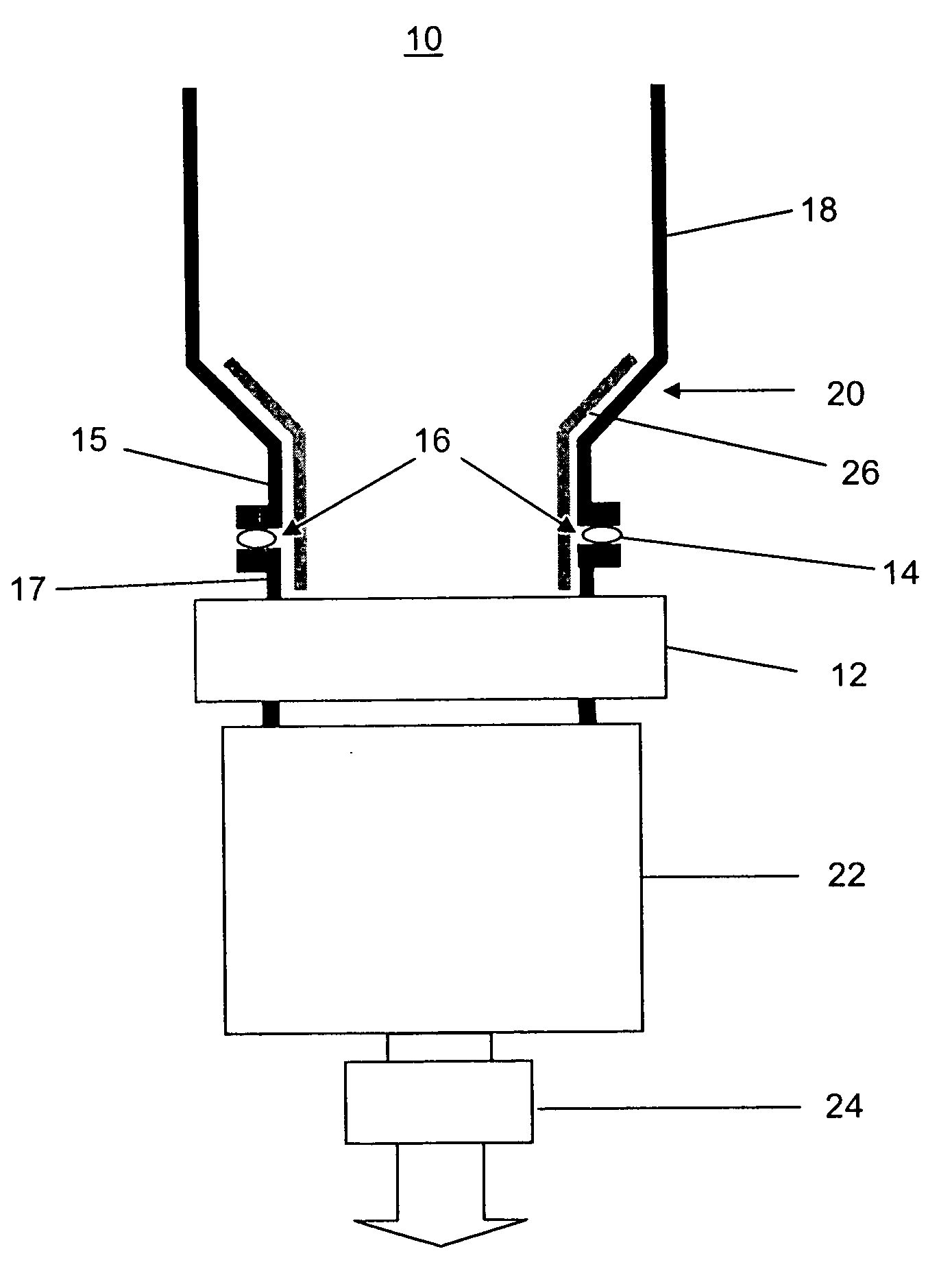
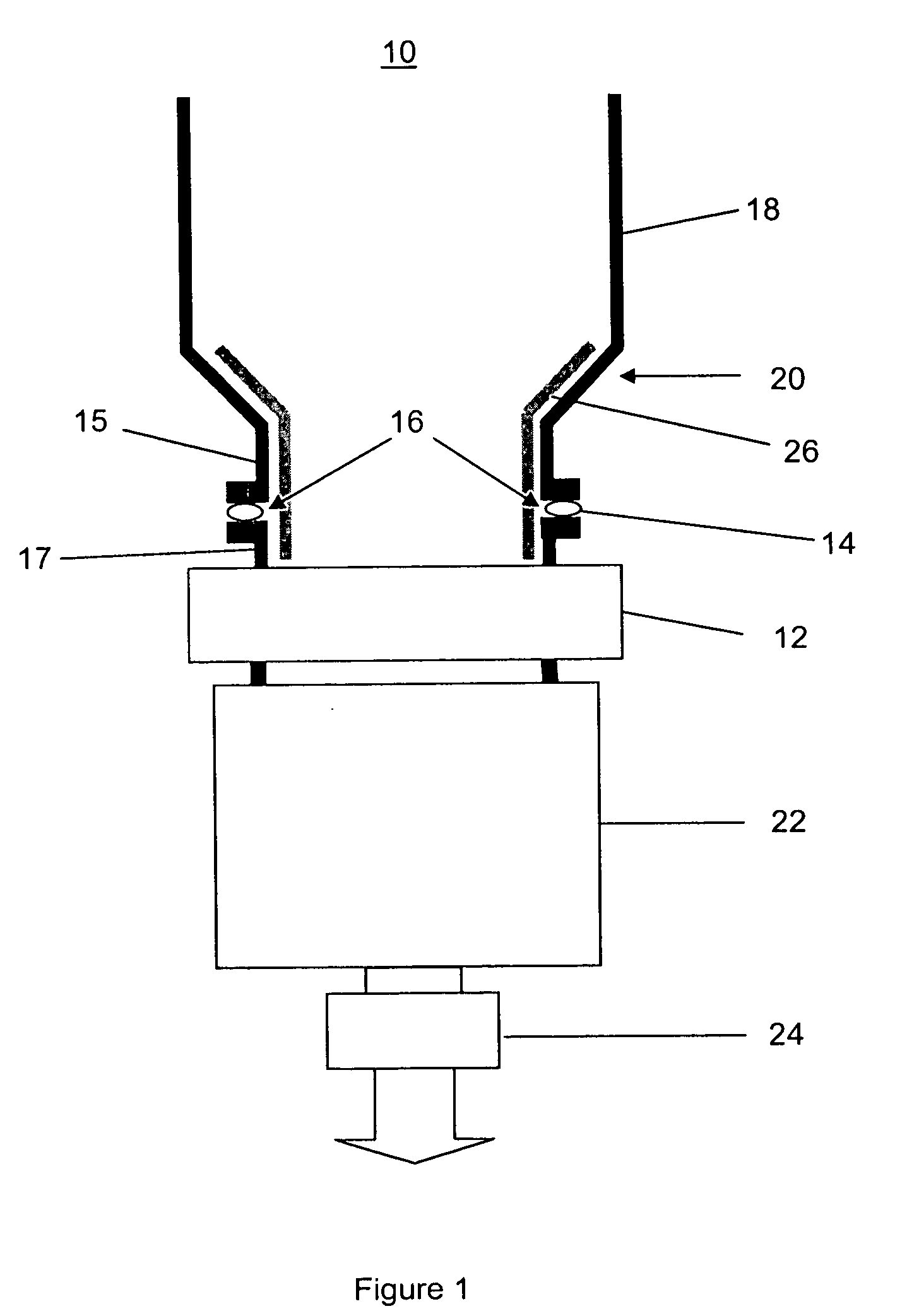
[0019]A schematic cross-sectional view of part of an AMAT DPS etch chamber 10, is shown in FIG. 1. The etch chamber 10 comprises a gate valve 12 connected to the etch chamber 10 and an O-ring 14 disposed between the etch chamber 10 and the gate valve 12.
[0020]An internal gap 16 exists between a flange portion 17 of the gate valve 12 and a flange portion 15 of the etch chamber 10, with the O-ring 14 typically not filing the gap 16 in a manner that is flush with the adjoining inner wall portions of the etch chamber 10 and the gate valve 12.
[0021]The etch chamber 10 is connected to the gate valve 12 via the flange portions 15, 17 of the etch chamber 10 and the gate valve 12 respectively. As will be appreciated by a person skilled in the art, the flange portions 15, 17 are connected to each other utilising bolts and nuts (not shown), with the O-ring 14 disposed therebetween for sealing engagement of the flange portions 15 and 17.
[0022]A turbo pump 22 is connected to the gate valve 12 o...
second embodiment
[0026]FIGS. 3(a) and (b) show photographs of an internal view of an etch chamber 300 without and with a liner inserted respectively, in a In FIG. 3(a), the gap 302 between a flange portion 304 of the gate valve 308 and a flange portion 306 of the etch chamber 300 is visible. In this embodiment, the flange portion 306 forms part of a port portion 310 of the etch chamber 300.
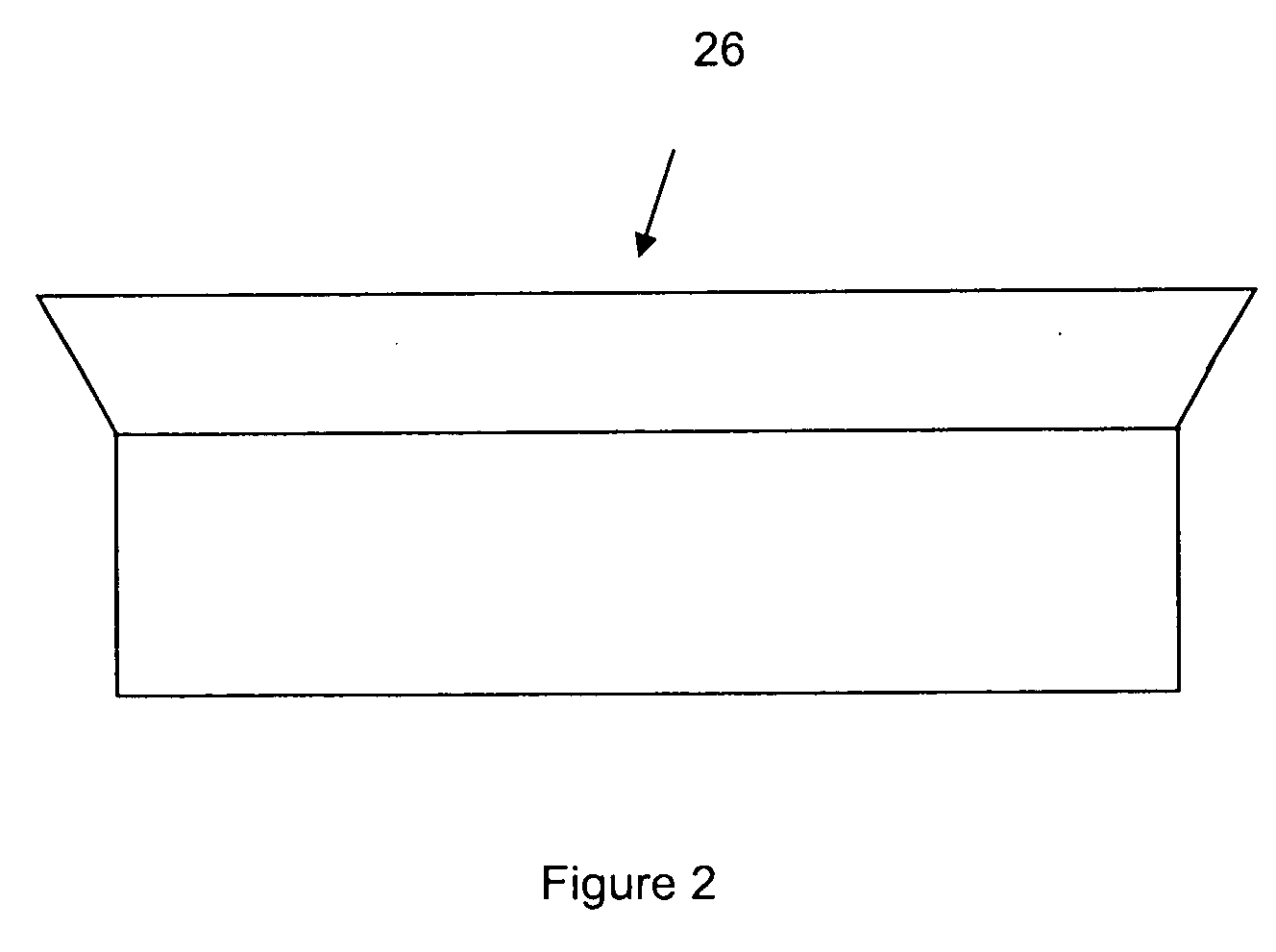
[0027]As shown in FIG. 3(b), the inserted liner 312 covers the gap 302 (FIG. 3(a)), to advantageously eliminate build up of particles in the gap 302 (FIG. 3(a)), to minimize, and possibly eliminate, the flow of particles back into the etch chamber 300. In this example embodiment, the liner 312 has a curved rim 314, to further minimize or eliminate build up of particles at the rim 314 of the liner 312.
third embodiment
[0028]It will be appreciated that the etch chamber may be connected to other types of valves such as a throttling gate valve. In a third embodiment where a throttling gate valve is connected to the etch chamber, the problem of particles flowing back into the etch chamber without using a liner to cover the gap between the etch chamber and the valve was found to be severe as the throttling gate valve is opened and closed continuously to maintain the required pressure in the etch chamber. With a liner having a profile corresponding with an internal profile of a flange portion of the etch chamber and a flange portion of the valve to cover the gap, build up of particles in the gap can advantageously be eliminated. Thus the flow of particles back into the etch chamber can be greatly minimised, and possibly eliminated, resulting in improved performance of the etch chamber.
[0029]It will be appreciated by a person skilled in the art that numerous variations and / or modifications may be made t...
PUM
| Property | Measurement | Unit |
|---|---|---|
| thickness | aaaaa | aaaaa |
| shape | aaaaa | aaaaa |
| pressure | aaaaa | aaaaa |
Abstract
Description
Claims
Application Information