Water resistant keycard reader assembly for an electronic lock

a keycard reader and electronic lock technology, applied in the field of door locks, can solve problems such as the inoperableness of the entire electronic lock

Inactive Publication Date: 2007-07-19
COMPIZED SECURITY SYST +1
View PDF7 Cites 10 Cited by
  • Summary
  • Abstract
  • Description
  • Claims
  • Application Information

AI Technical Summary

Benefits of technology

[0005] An electronic lock according to the present invention includes a keycard sensing assembly which interacts with a keycard sensing switch is mounted directly to a surface of a circuit board. The keycard sensing assembly is located adjacent a keycard slot such that when a key card is fully inserted into the keycard slot, the keycard activates the keycard sensing assembly. Such an arrangement permits a significant portion of the circuit board to be potted within a potting compound such that the keycard reader becomes essentially waterproof. Such a construction permits the insertion of a wet or damp keycard without concern for water damage to the electronics.

Problems solved by technology

Disadvantageously, hotel guests and the like often insert keycards which have been submersed in water such as from the guest being in a pool or spa.
Although not damaging to the keycard, repeated introduction of moisture into the interior of the electronic lock may render the keycard sensing switch or other electronic components in communication with the keycard slot inoperable.
Failure of an electronic lock component may render the entire electronic lock inoperable.

Method used


Image

  • Water resistant keycard reader assembly for an electronic lock
  • Water resistant keycard reader assembly for an electronic lock
  • Water resistant keycard reader assembly for an electronic lock

Examples


Embodiment Construction

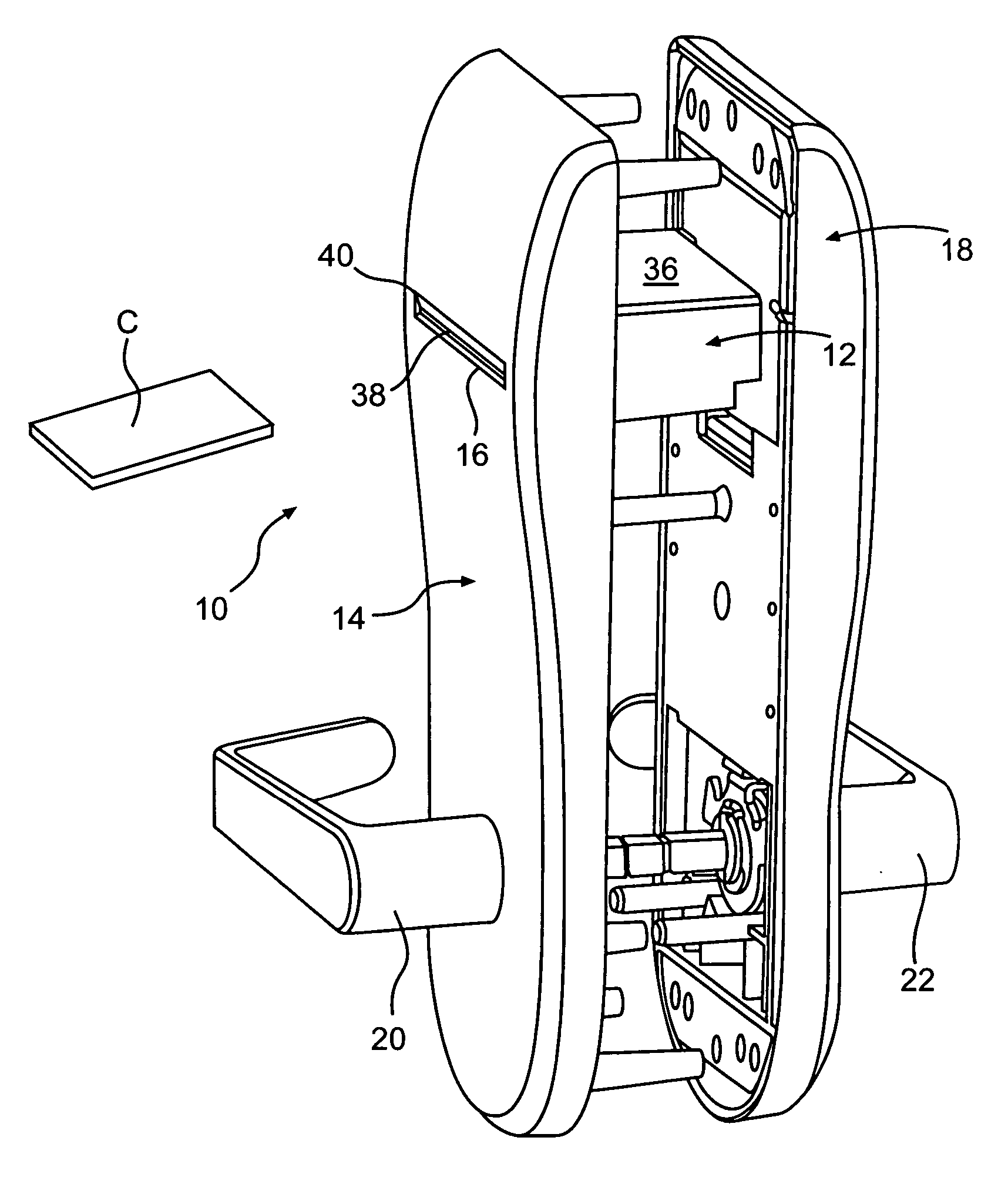
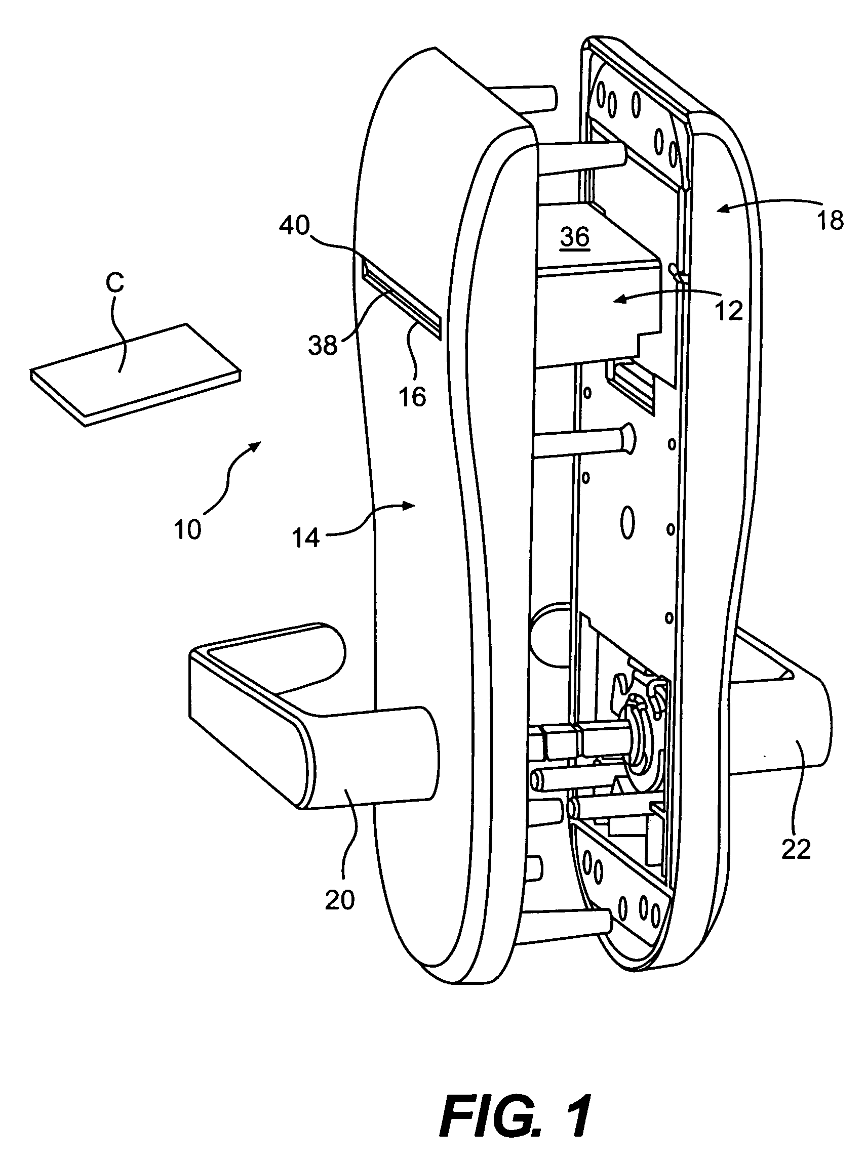
[0017]FIG. 1 illustrates a general perspective view of a lock 10 having a keycard reader 12. The lock 10 includes a front trim panel 14 having a trim slot 16 through which an electronic key card C is received. A corresponding rear trim panel 18 is attachable to the front trim panel 14 with the keycard reader 12 mounted therebetween. The rear trim panel 18 is oriented by a door toward the interior of a room when the lock 10 is installed and therefore does not include a keycard slot like the front trim panel 14. Manually operable door handles 20, 22 operate a retractable latch bolt24 (FIG. 2) in any conventional manner in response to a valid electronic key card.

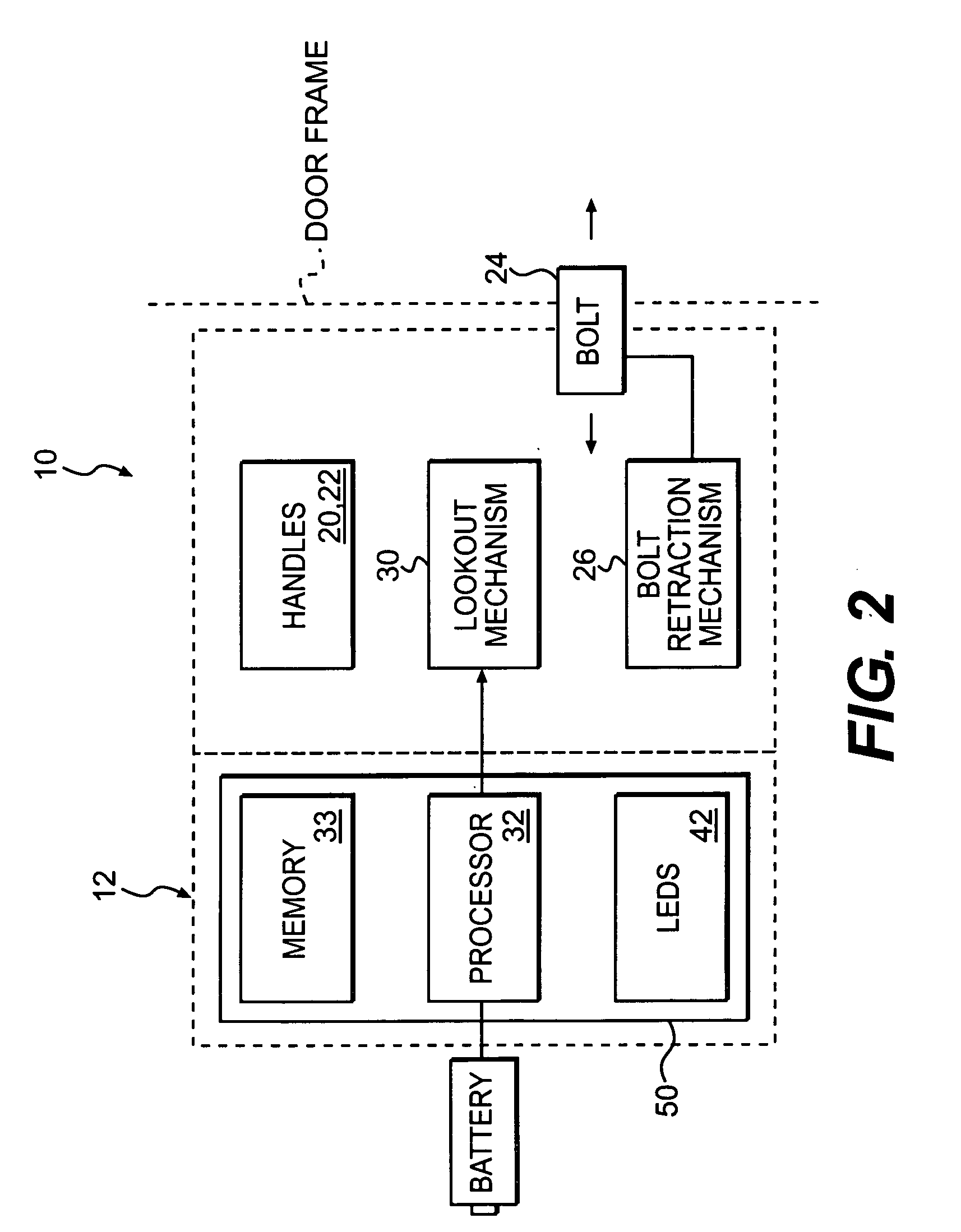
[0018] As schematically represented in block form at FIG. 2, the keycard reader 12 is operably coupled to the retractable latch bolt 24 via any desired bolt retraction mechanism 26. The latch bolt 24 is operably connected to the handles 20, 22 so that the latch bolt 24 is movable between an extended position and a retracted po...


PUM


Abstract

An electronic lock includes a keycard sensing assembly which interacts with a keycard sensing switch surface mounted to a circuit board. The keycard sensing assembly is located adjacent a rear of a keycard slot such that when a key card is fully inserted into the keycard slot, the keycard activates the keycard sensing assembly. Such an arrangement permits a significant portion of the circuit board to be potted within a potting compound such that the keycard reader becomes essentially waterproof. Such a construction permits the insertion of a wet or damp keycard without concern for water damage to the keycard sensing assembly.

Description

BACKGROUND OF THE INVENTION [0001] The present invention relates to door locks, and more particularly to door locks having an electronic key card reader. [0002] Door locks in properties such as hotels often use electronic key cards rather than mechanical keys to control operation of a lock. Electronic key cards and electronic locks are individually programmable and provide significant security in a convenient manner. [0003] Electronic locks are typically self-powered through an internal battery. In addition to the electronic lock operational components, electronic locks provide visual feedback in the form of indicator lights that illuminate in response to card insertion and / or removal. All of these electrical components are powered by the internal battery. To maximize the operational life of the battery so as to minimize maintenance of the electronic lock, a keycard sensing switch powers up the electronics of the electronic lock only in response to insertion and contact with a keyca...

Claims


Application Information

Patent Timeline
Patent Type & Authority Applications(United States)
IPC IPC(8): H01H27/00
CPCG07C9/00904H01H27/00G07C9/00944
Inventor MITCHELL, ERNSTURBEN, BRYANMOON, CHARLES
Owner COMPIZED SECURITY SYST
Why Eureka
Try Eureka