Methods and systems for controlling the temperature stability of an inductor

a technology of temperature stability and inductance, which is applied in the direction of pulse technique, measurement leads/probes, instruments, etc., can solve the problems source of temperature drift error, and relatively harsh environment in which the proximity probe operates, and achieves substantial constant resistance versus temperature profile of the coil

Active Publication Date: 2007-07-19
BAKER HUGHES HLDG LLC
View PDF29 Cites 1 Cited by
  • Summary
  • Abstract
  • Description
  • Claims
  • Application Information

AI Technical Summary

Problems solved by technology

The environment that the proximity probe operates may be relatively harsh.
Moreover, the sensing coil of the proximity probe usually contains sources of temperature drift error which are attempted to be compensated for in the final product.
A source of the temperature drift error in the sensing coil is due to a temperature dependent resistance of the coil and an inductance of the coil.
This temperature dependent resistance and inductance of the sensing coil effects a source of temperature drift error resulting in inaccurate proximity probe measurements as a consequence of the false appearance of a gap change between the target and sensing coil.
Such inconsistencies in temperature stability of the proximity probe result in unpredictable and unreliable measurements even when the proximity probe is functioning in its linear range of operation.
Compensation for such inconsistencies is usually only partially effective to facilitate temperature dependent errors.

Method used


Image

  • Methods and systems for controlling the temperature stability of an inductor
  • Methods and systems for controlling the temperature stability of an inductor
  • Methods and systems for controlling the temperature stability of an inductor

Examples


Embodiment Construction

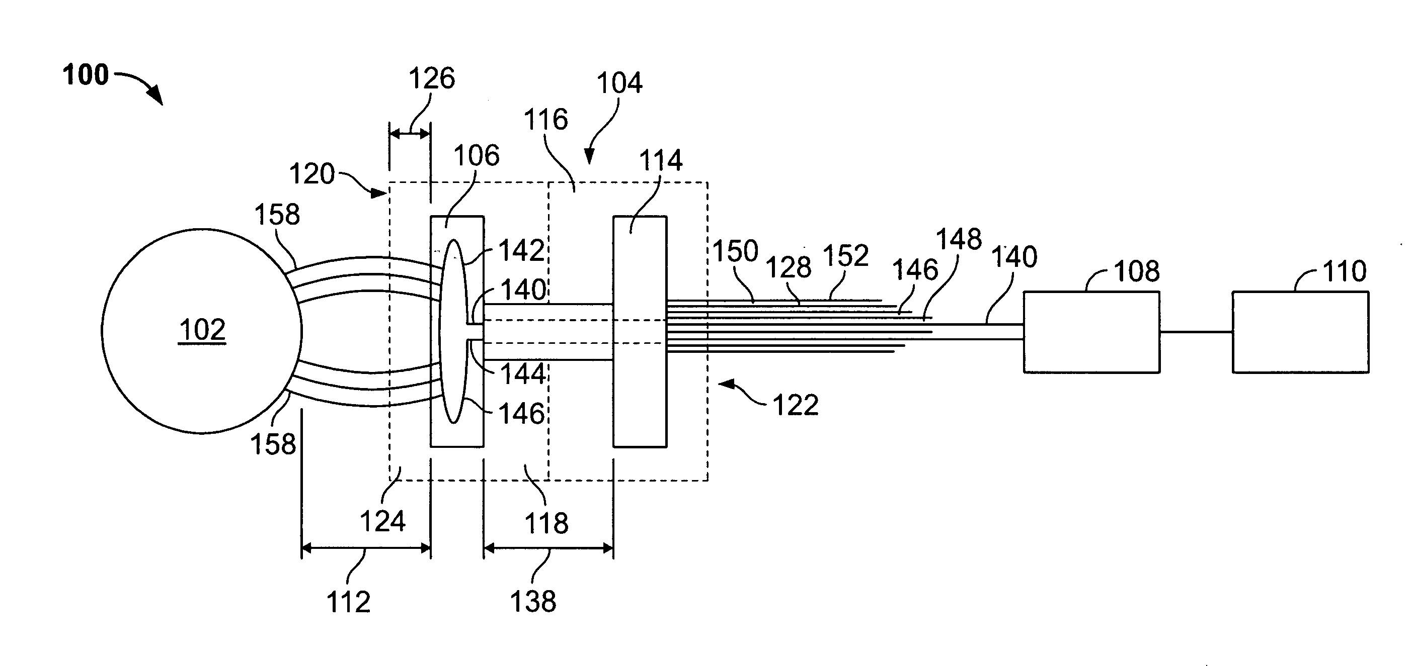
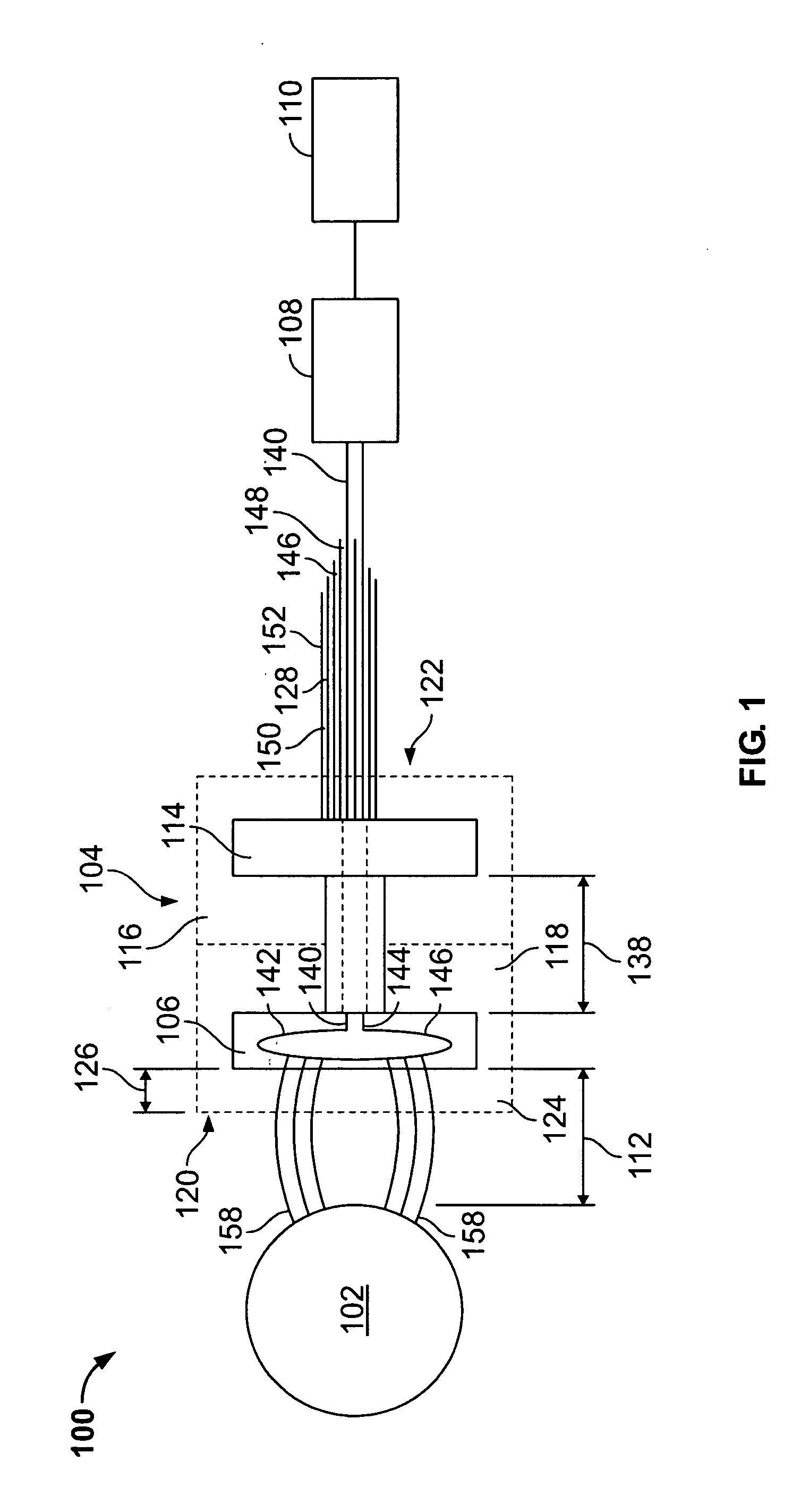
[0013]FIG. 1 is a schematic view of a proximity probe system 100. Proximity probe system 100 is configured to monitor a target object, for example, a rotating shaft 102 of a machine (not shown). Proximity probe system 100 includes a proximity probe 104 including a temperature stable inductor 106, an electronic circuit 108 and a monitoring system 110. Typically, proximity probe 104 is operatively coupled to electronic circuit 108 and is positioned adjacent rotating shaft 102 for monitoring the vibrational or rotor position characteristics thereof. Proximity probe 104 uses eddy currents to generate a signal indicative of a gap 112 between rotating shaft 102 and inductor 106. Proximity probe 104 includes a tuning disk 114 magnetically coupled to inductor 106 for setting a scale range for the output of proximity probe 104.

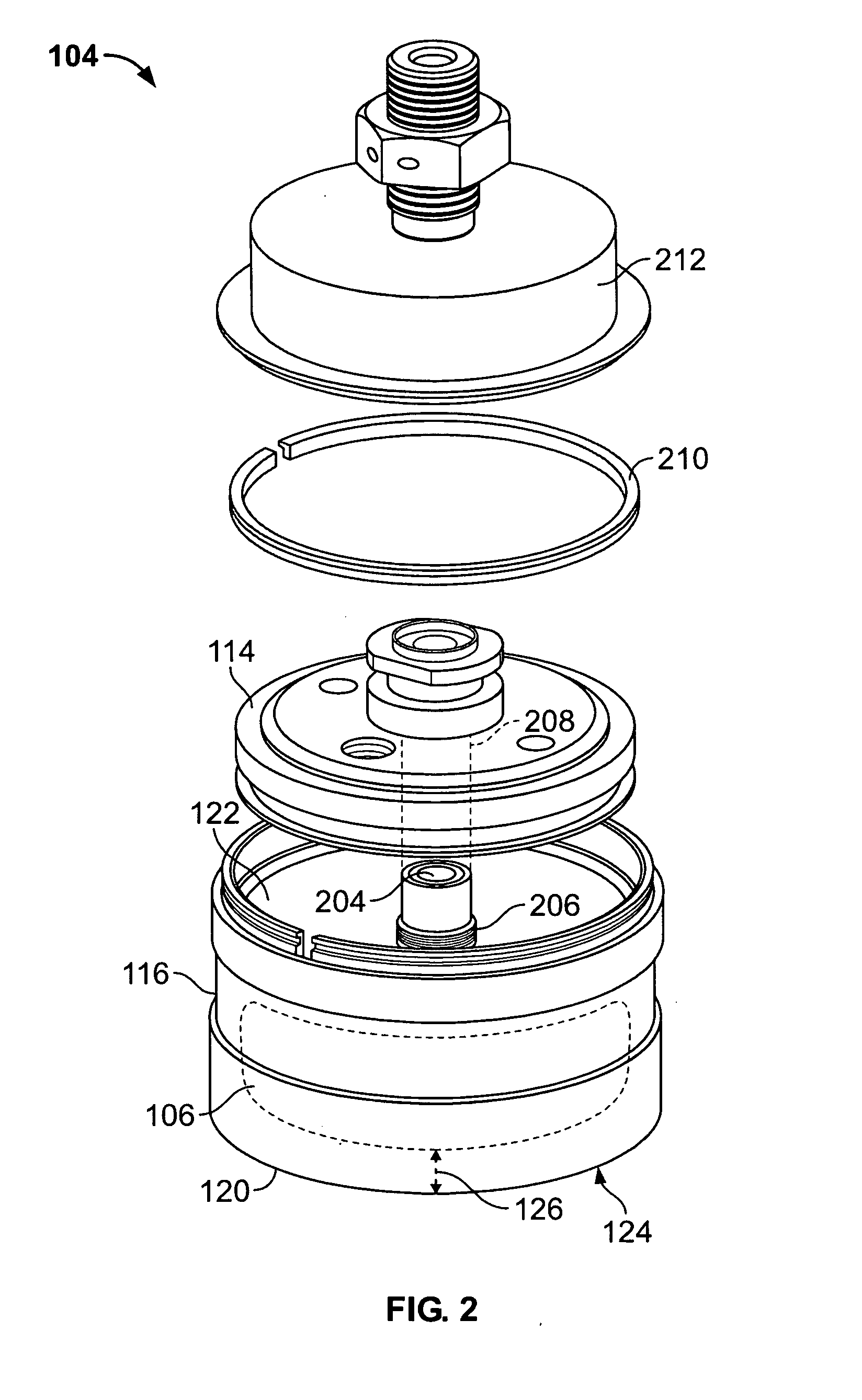
[0014] Proximity probe 104 defines a common enclosure 116 housing both inductor 106 and tuning disk 114. In the exemplary embodiment, proximity probe 104 is formed fr...


PUM


Abstract

Methods and systems a method of assembling a proximity probe are provided. The method includes determining a coil wire dimension and coil geometry for the probe such that a resistance versus temperature profile of the coil is approximately constant when the coil is excited with an excitation frequency of approximately 150 kilohertz to approximately 350 kilohertz, and adjusting the coil geometry such that a resistance versus temperature profile of the coil is substantially constant.

Description

BACKGROUND OF THE INVENTION [0001] This invention relates generally to controlling the temperature stability of an inductor, and more particularly to methods and apparatus for controlling the temperature stability of a sensing coil of a proximity probe. [0002] At least some known rotating and reciprocating machinery use an eddy current or proximity probe to facilitate monitoring machine vibration or rotor position characteristics. The environment that the proximity probe operates may be relatively harsh. [0003] Typically, the proximity probe, outputs a signal correlative to a spacing between a target object such as, a rotating shaft of a machine or an outer ring of a rolling element bearing and a sensing coil of the proximity probe. The gap or spacing between the target and the sensing coil of the proximity probe needs to remain within the linear range of the proximity probe for providing accurate and reliable measurements of machine vibration characteristics. Accordingly, to provid...

Claims


Application Information

Patent Timeline
Patent Type & Authority Applications(United States)
IPC IPC(8): G01B7/14
CPCG01B7/023H03K17/9505H03K17/9502G01R1/06
Inventor BOWLDS, BRIAN BURKET
Owner BAKER HUGHES HLDG LLC
Why Eureka
Try Eureka