In-vehicle radar device and communication device

Inactive Publication Date: 2007-07-19
CALSONIC KANSEI CORP +1
View PDF29 Cites 154 Cited by
  • Summary
  • Abstract
  • Description
  • Claims
  • Application Information

AI Technical Summary

Benefits of technology

[0009] Moreover, according to the present invention, it is possible to obtain the direction and distance from location information overlapped with the radar wave from othe

Problems solved by technology

However, a study has not been carried out yet on combining the measurement of distance to other vehicle around the own vehicle within a short distance and the vehicle-to-vehicle communication, and it is thu

Method used


Image

  • In-vehicle radar device and communication device
  • In-vehicle radar device and communication device
  • In-vehicle radar device and communication device

Examples


embodiment 1

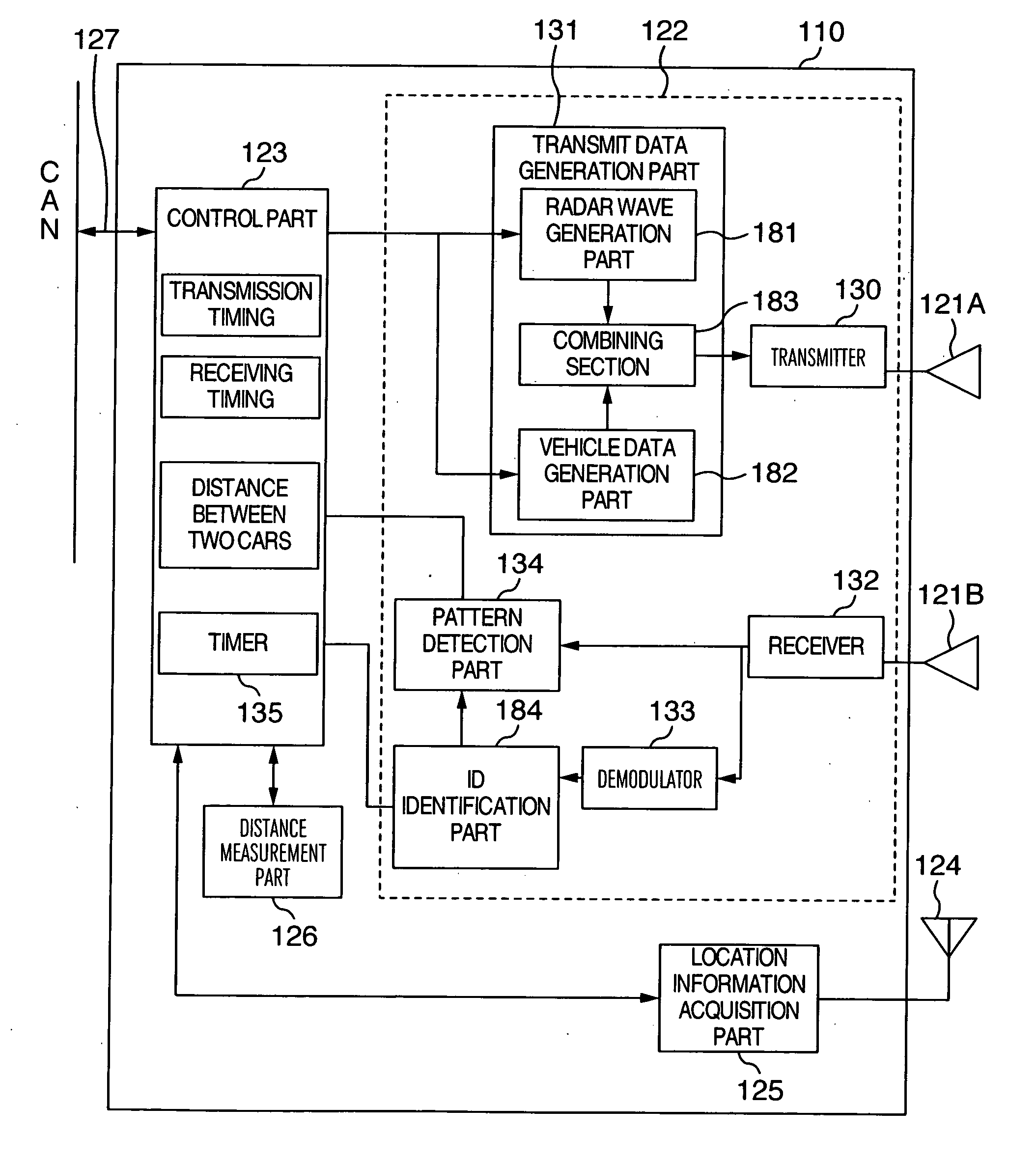
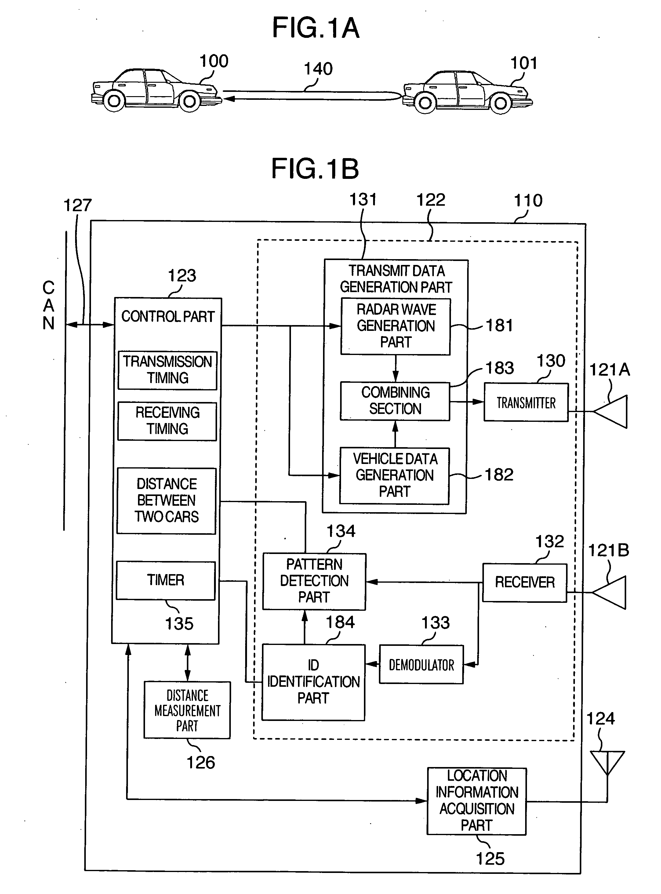
[0029] An example of the configuration of an in-vehicle radar device using the present invention is described with reference to FIG. 1A and FIG. 1B. In FIG. 1A, an in-vehicle radar device 110 using the present invention shown in FIG. 1B is mounted on an own vehicle 100. A location information acquisition part 125 mounted in the in-vehicle radar device 110 receives signal from a GPS satellite via an antenna 124, and measures its own position to transmit this to a vehicle-to-vehicle distance measurement part 126. In addition, although this location information acquisition part indicates a GPS by way of example, other location information acquisition method may be employed.

[0030] In the in-vehicle radar device 110, a control part 123 sends to a radar transceiver 122 a command to transmit a radar wave in a predetermined cycle or at a timing determined according to the driving speed. In the control part 123, a timing at which this command to transmit was made is read from a timer 135 an...


PUM


Abstract

In order to consider an optimum control method and an optimum mounting method needed, a UWB having a communication function and a radar function are used. For an obstacle vehicle in front, the distance between two cars is measured using the radar function, and according to this distance, a hazard warning is issued to a driver or a pre-crash operation is carried out. Moreover, by informing its own position to each other between vehicles using the communication function, the distance to a vehicle near to the own vehicle is measured regardless of clutter, and according to this distance, a hazard warning is issued to a driver or a pre-crash operation is carried out. Moreover, the operating frequency and transmission power of a radar are changed based on its own location information, thereby reducing influence to and from other wireless system.

Description

BACKGROUND OF THE INVENTION [0001] The present invention relates to a wireless device having a radar function mounted in a high speed vehicle, and also relates to a radar system having a communication function between the wireless devices. [0002] In order to improve safety in vehicles, millimeter wave radars have been put in practical use since around 1999. This millimeter wave radar allows accurate measurement of the distance between two cars even under adverse weather conditions as compared with the conventional infrared radar. The millimeter wave radar is mounted to the front of a vehicle, and from the information obtained from the radar, the distance and relative speed between a leading car and its own car are detected. Then, operations such as controlling to make the distance between two cars constant and the like are carried out according to the detected distance between two cars and relative speed. [0003] However, the application of millimeter wave radars remains to some of l...

Claims


Application Information

Patent Timeline
IPC IPC(8): G01S13/93G01S13/08G01S13/931
CPCG01S7/006G01S7/023G01S13/931G01S2013/9382G01S2013/936G08G1/161G01S2013/9353G01S2013/9325G01S2013/93273G01S2013/9316G01S2013/932G01S7/0232
Inventor SUZUKI, HIDEYAHANAWA, KAZUHIKO
Owner CALSONIC KANSEI CORP
Why Eureka
Try Eureka