Arrangement, method and computer program for controlling a computer apparatus based on eye-tracking

a computer and eye-tracking technology, applied in the field of computer-based eye-tracking systems, can solve the problems of device miss the mark in one or several respects, the input ditto has been substantially unchanged, and the communication band-width of the human computer interaction is severe, so as to achieve the effect of minimal amount of double processing and efficient man-machin

Active Publication Date: 2007-07-19
TOBII TECH AB
View PDF12 Cites 118 Cited by
  • Summary
  • Abstract
  • Description
  • Claims
  • Application Information

AI Technical Summary

Benefits of technology

[0009] The object of the present invention is therefore to provide a holistic means of controlling a computer apparatus based on a user's ocular activity, which alleviates the above problems and thus offers an efficient man-machine interaction with a minimal amount of double processing, i.e. wherein as much as possible of the eye-tracking data processing is performed centrally in respect of GUI-components that may belong to two or more separate applications.

Problems solved by technology

Nevertheless, while the output bandwidth has multiplied several times, the input ditto has been substantially unaltered.
Consequently, a severe asymmetry in the communication band-width in the human computer interaction has occurred.
However, in many cases these devices miss the mark in one or several respects.
One problem is that the prior-art solutions fail to take a holistic view on the input interfaces to the computer.
Typically, this leads to fatigue symptoms and a degree of discomfort experienced by the user.
This is particularly true if an eye tracker is used to control a cursor on a graphical display, and for various reasons the eye tracker fails to track the user's point of regard sufficiently well, so that there is a mismatch between the user's actual point of regard and the position against which the cursor is controlled.
Although this strategy may indeed enhance the efficiency of the man-machine interaction, no multimodal solution has yet been presented according to which eye-tracking data is processed optimally.
Thus, any processing of eye tracking data in respect of a first application cannot be reused by a second application, and vice versa.
Naturally, in such a case, there is a high risk that the different applications perform a substantial amount of overlapping eye-tracking data processing.

Method used


Image

  • Arrangement, method and computer program for controlling a computer apparatus based on eye-tracking
  • Arrangement, method and computer program for controlling a computer apparatus based on eye-tracking
  • Arrangement, method and computer program for controlling a computer apparatus based on eye-tracking

Examples


first embodiment

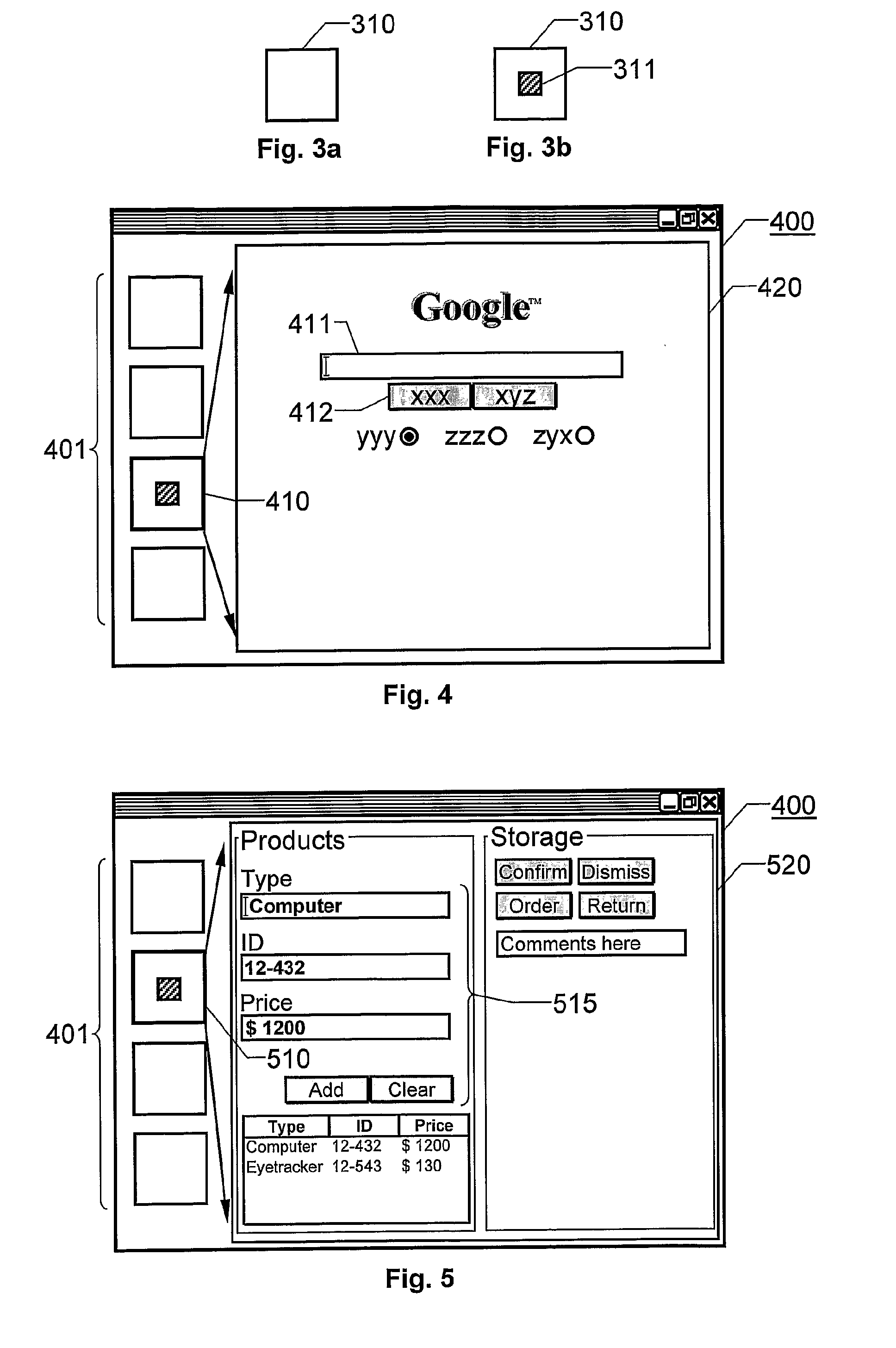
[0055]FIG. 4 illustrates a first embodiment according to the invention, where a proposed multiview toolbar 401 is used to control applications in a frame 400. The multiview toolbar 401 here includes four different eye-buttons, which each may contain a thumbnail image (not shown) of a respective application with which the button is associated. A first button 410 is associated with a first application, e.g. an Internet browser, which preferably accesses a predefined URL or web page. The first application has a user interface which here is represented by a sub-frame 420 within the frame 400. Hence, by viewing the first button 410, the user may open the sub-frame 420. Either this activation is accomplished after a particular gaze dwell time in respect of the button 410, or in response to an activation signal, for example a keystroke or a control word. Then, a search may be executed by viewing a text input box 411, entering relevant search terms, and thereafter manipulating a search butt...

second embodiment

[0056]FIG. 5 illustrates a second embodiment according to the invention based on the proposed multiview toolbar 401. Here, a second button 510 is associated with a second application, e.g. a product management system, which has a user interface in the form of a sub-frame 520 within the frame 400. This means that a user may activate the second application by viewing the second button 510 during a particular gaze dwell time, or generating a separate activation signal (as mentioned above). Preferably, a default set of text input boxes and buttons 515 are activated initially. Then, by viewing other areas within the sub-frame 520, alternative fields and functions may be activated and manipulated.

third embodiment

[0057] Particularly, a screen control may be adapted to expand upon a manipulation based on a user's ocular activity. FIGS. 6a and 6b illustrate this as a third embodiment according to the invention.

[0058] Here, a text field 620 in the sub-frame 520 occupies a relatively small area on the display as long as the eye-tracking data signal indicates that the user's point of regard lies outside this field 620. However if, according to the eye-tracking data signal, the point of regard reaches a particular dwell time within the display area represented by the text field 620, this field expands, for instance as shown in the FIG. 6b. Hence, more information than what was initially visible in the field 620 may be shown. The thus expanded text field 620 may even cover graphical objects which otherwise are shown in the frame 400. This is advantageous, because thereby the information may be presented on-demand, so that the frame 400 and the sub-frame 520 contain more data than what actually can ...


PUM


Abstract

A computer based eye-tracking solution is disclosed. A computer apparatus is associated with one or more graphical displays (GUI components) that may be manipulated based on user-generated commands. An event engine is adapted to receive an eye-tracking data signal that describes a user's point of regard on the display. Based on the signal, the event engine is adapted to produce a set of non-cursor controlling event output signals, which influence the GUI-components. Each non-cursor controlling event output signal describes a particular aspect of the user's ocular activity in respect of the display. Initially, the proposed event engine receives a control signal request from each of the GUI-components. The control signal request defines a sub-set of the set of non-cursor controlling event output signals which is required by the particular GUI-component. The event engine delivers non-cursor controlling event output signals to the GUI-components in accordance with each respective control signal request.

Description

THE BACKGROUND OF THE INVENTION AND PRIOR ART [0001] The present invention relates generally to computer based eye-tracking systems. More particularly the invention relates to an arrangement for controlling a computer apparatus according to the preamble of claim 1 and a corresponding method according to the preamble of claim 11. The invention also relates to a computer program according to claim 21 and a computer read-able medium according to claim 22. [0002] The human computer interaction was revolutionized by the introduction of the graphical user interface (GUI). Namely, thereby, an efficient means was provided for presenting information to a user with a bandwidth which immensely exceeded any prior channels. Over the years the speed at which information can be presented has increased further through color screens, enlarged displays, intelligent graphical objects (e.g. pop-up windows), window tabs, menus, toolbars and sounds. During this time, however, the input devices have remai...

Claims


Application Information

Patent Timeline
Patent Type & Authority Applications(United States)
IPC IPC(8): G09G5/00G06F3/00G06F3/01G06F3/0346G06F3/048G06F3/0484
CPCG06F3/017G06F3/013
Inventor BJORKLUND, CHRISTOFFERESKILSSON, HENRIKJACOBSON, MAGNUSSKOGO, MARTEN
Owner TOBII TECH AB
Why Eureka
Try Eureka