Pattern inspection apparatus and method and workpiece tested thereby

a technology of pattern inspection and workpiece, applied in the field of workpiece pattern inspection technologies, can solve the problems of limited inspection capabilities of the method taught thereby, lack of practical applicability, troublesome and time-consuming data processing, etc., and achieve the effect of high-quality inspection

Inactive Publication Date: 2007-07-19
ADVANCED MASK INSPECTION TECH
View PDF1 Cites 8 Cited by
  • Summary
  • Abstract
  • Description
  • Claims
  • Application Information

AI Technical Summary

Benefits of technology

[0008] It is therefore an object of this invention to provide a pattern inspection method and apparatus capable of performing highly accurate inspection while offering an ability to find emphatic portions of defects temporarily appearing in the process of transfer / development simulation of the image of a workpiece being tested. It is another object of the invention to obtain a workpiece that is tested by the pattern inspection method and apparatus.
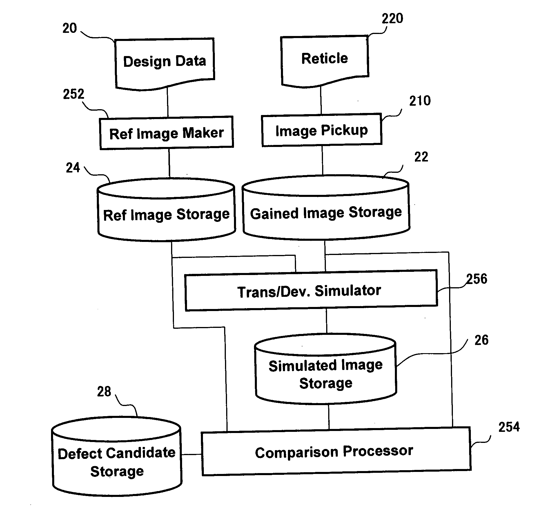
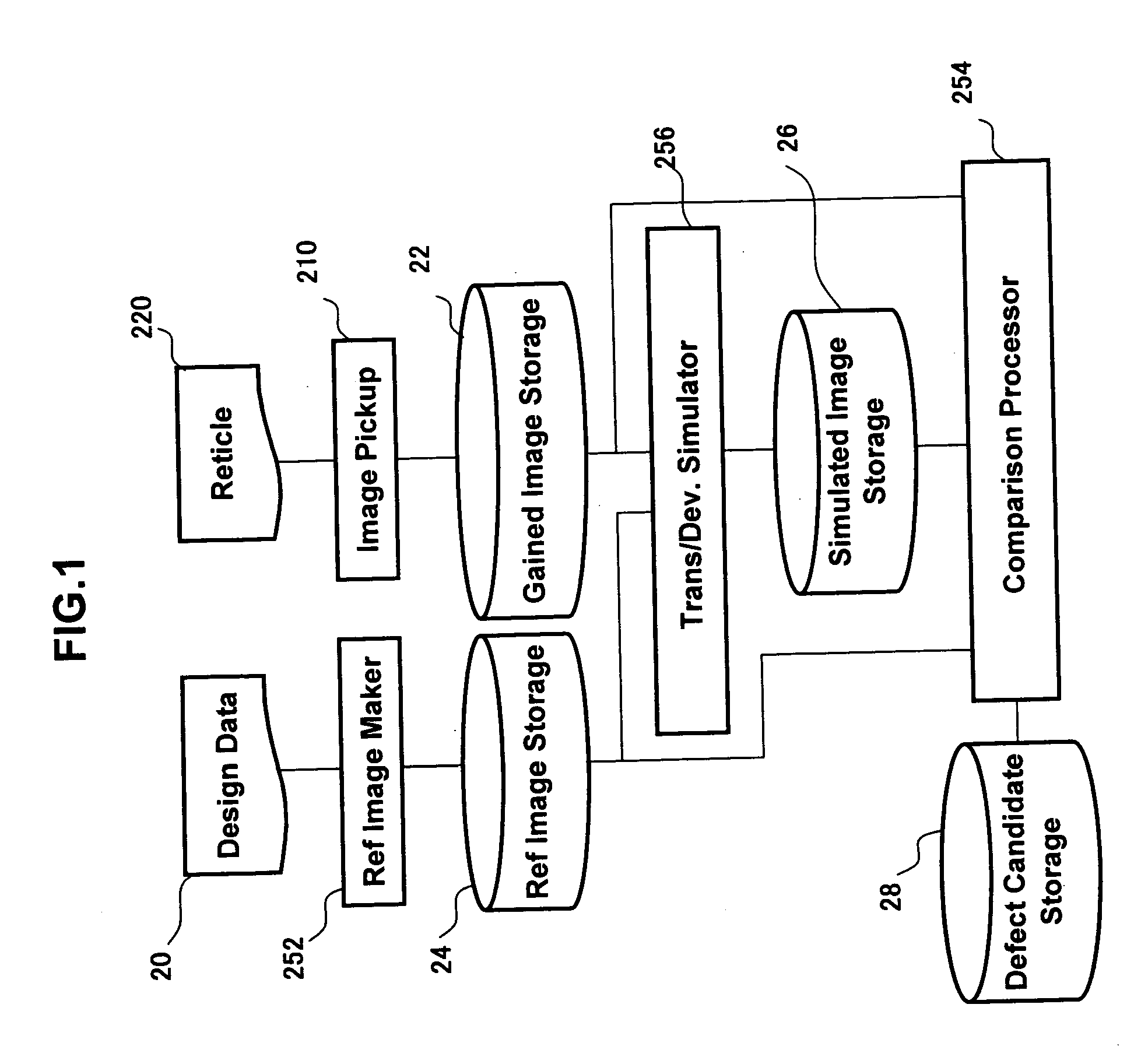
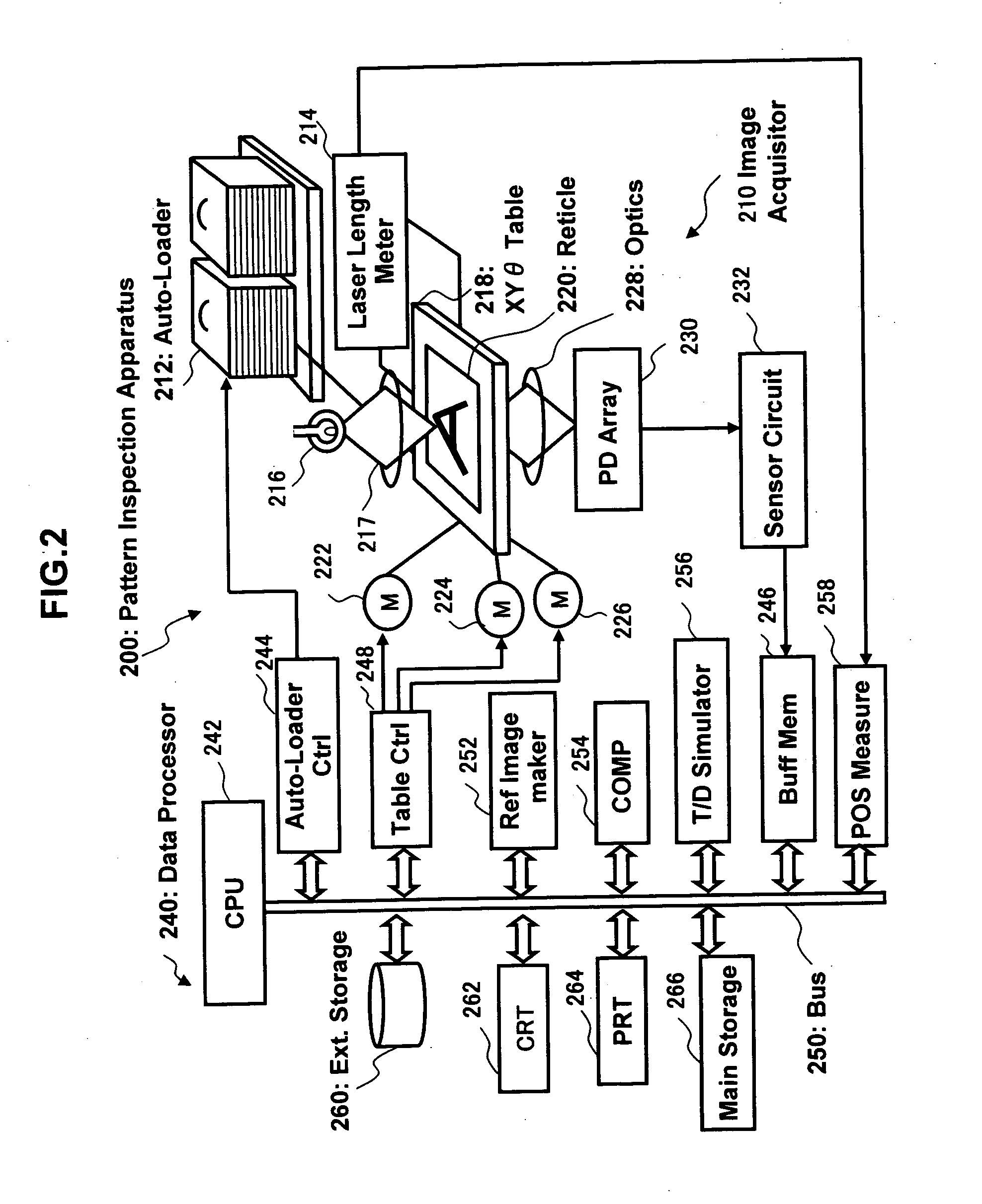
[0009] Currently preferred embodiments of the invention are arranged to perform simulation processing under ordinary or “standard” process conditions of a workpiece to be inspected, such as a reticle. Pattern inspection is carried out in mid course of the simulation, thereby finding defect candidates on a real time basis. This avoids the need to establish every possible set of process conditions. A high precision level of or “detailed” simulation processing is applied only to such defect candidates thus found, so it becomes possible to achieve inspection with enhanced accuracy. This makes it possible to efficiently check the workpiece for defects. More particularly, but not exclusively, the invention may be implemented in several forms which follow.

Problems solved by technology

Unfortunately this method as taught thereby suffers from limited inspection capabilities.
This would require troublesome and time-consuming data processing and thus lacks practical applicability.

Method used


Image

  • Pattern inspection apparatus and method and workpiece tested thereby
  • Pattern inspection apparatus and method and workpiece tested thereby
  • Pattern inspection apparatus and method and workpiece tested thereby

Examples


example 1

[0036] Turning to FIG. 7, an exemplary procedure at the transfer / development simulation step S2 of FIG. 4 is shown, which performs DD comparison of a couple of dies 32a and 32b in a pattern image acquired from the reticle 220 being in mid course of transfer / development simulation while letting one of these dies, 32a, be the pattern image to be tested and letting the other die 32b be a fiducial or “base” pattern image. The procedure shown herein starts with a step which applies the same transfer / development simulation to both the to-be-tested die 32a and the fiducial die 32b, thereby to form a to-be-tested pattern and a fiducial pattern of latent images 36a and 36b of the tested die 32a and fiducial die 32b. Then, apply transfer / development simulation to these tested and fiducial patterns of the latent images 36a-36b of dies 32a-32b. At a time point (i=n) in mid course of the transfer / development simulation step S2, let the comparison processor 254 compare together the patterns of du...

example 2

[0037] Another exemplary procedure is shown in FIG. 8. This procedure includes applying transfer / development simulation to a sensed image 32a of to-be-tested die on the reticle 220 and a reference image 56 as created from the design data of a fiducial die of reticle 220 and performing DB comparison between the to-be-tested pattern of a midstream image 38a and the fiducial pattern of a midstream image 38b, which are obtainable at the transfer / development simulation step S2 of FIG. 4. This example is similar to that shown in FIG. 7 except that the fiducial pattern used in the former is a reference image. Regarding the other process steps also, these are the same in principle as those of FIG. 7.


PUM

PropertyMeasurementUnit
clock frequencyaaaaaaaaaa
thresholdaaaaaaaaaa
defectaaaaaaaaaa

Abstract

A pattern inspection apparatus capable of finding temporary emphatic portions in the process of transfer-and-development simulation of the image of a workpiece being tested is disclosed. This apparatus includes a first storage unit for retaining therein the pattern of an image captured from a workpiece under testing, a simulator for applying transfer / development simulation to the captured image pattern, and a second storage unit for storing the pattern of an image which is being presently simulated during the transfer / development simulation of the originally captured image pattern. A comparison processor handles as a pattern to be tested a pattern of the presently simulated or “midstream” image of the captured image while using a pattern to be compared as a fiducial pattern and compares the to-be-tested image to the fiducial pattern. A pattern inspection method is also disclosed.

Description

CROSS-REFERENCE TO RELATED APPLICATION [0001] This application claims priority to Japanese Patent Application No. 2006-010760, filed Jan. 19, 2006, the disclosure of which is incorporated herein by reference. BACKGROUND OF THE INVENTION [0002] 1. Field of the Invention [0003] The present invention relates generally to workpiece pattern inspection technologies and, more particularly, to a method and apparatus for inspecting for defects the pattern of a photomask, called “reticle,” which is used in the manufacture of semiconductor devices and liquid crystal display (LCD) panels. This invention also relates to a workpiece tested by the pattern inspection apparatus and method. [0004] 2. Description of Related Art [0005] Prior known pattern inspection methodology includes methods for applying simulation processing to a photomask of highly integrated circuit devices to thereby inspect the mask for defects. An example of the inspection methods is disclosed in Published Translated Internati...

Claims


Application Information

Patent Timeline
Patent Type & Authority Applications(United States)
IPC IPC(8): G06K9/00G01N21/956G03F1/84
CPCG01N21/95607G06T2207/30148G06T7/001
Inventor MATSUMURA, KENICHISAITO, YASUKO
Owner ADVANCED MASK INSPECTION TECH
Why Eureka
Try Eureka