Vane platform rail configuration for reduced airfoil stress

a technology of airfoil stress and platform rail, which is applied in the direction of machines/engines, liquid fuel engines, lighting and heating apparatus, etc., to achieve the effects of reducing thermal deflection resistance, reducing thermally induced stresses, and improving component durability

Active Publication Date: 2007-07-19
ANSALDO ENERGIA SWITZERLAND AG
View PDF4 Cites 19 Cited by
  • Summary
  • Abstract
  • Description
  • Claims
  • Application Information

AI Technical Summary

Benefits of technology

[0008] A turbine vane assembly for use in a gas turbine engine is disclosed having lower thermally induced stresses in the airfoil and platform region resulting in improved component durability. In an embodiment of the invention, the vane assembly comprises a first platform, a second platform positioned radially outward of the first platform, and at least one airfoil extending therebetween. The source of cracking in prior art vane assemblies related to the significant temperature differences over a short radial distance between the vane, platform, and fi

Problems solved by technology

The source of cracking in prior art vane assemblies related to the significant temperature differences over a short r

Method used


Image

  • Vane platform rail configuration for reduced airfoil stress
  • Vane platform rail configuration for reduced airfoil stress
  • Vane platform rail configuration for reduced airfoil stress

Examples


Embodiment Construction

[0021] The subject matter of the present invention is described with specificity herein to meet statutory requirements. However, the description itself is not intended to limit the scope of this patent. Rather, the inventors have contemplated that the claimed subject matter might also be embodied in other ways, to include different steps or combinations of steps similar to the ones described in this document, in conjunction with other present or future technologies. Moreover, although the terms “step” and / or “block” may be used herein to connote different elements of methods employed, the terms should not be interpreted as implying any particular order among or between various steps herein disclosed unless and except when the order of individual steps is explicitly described.

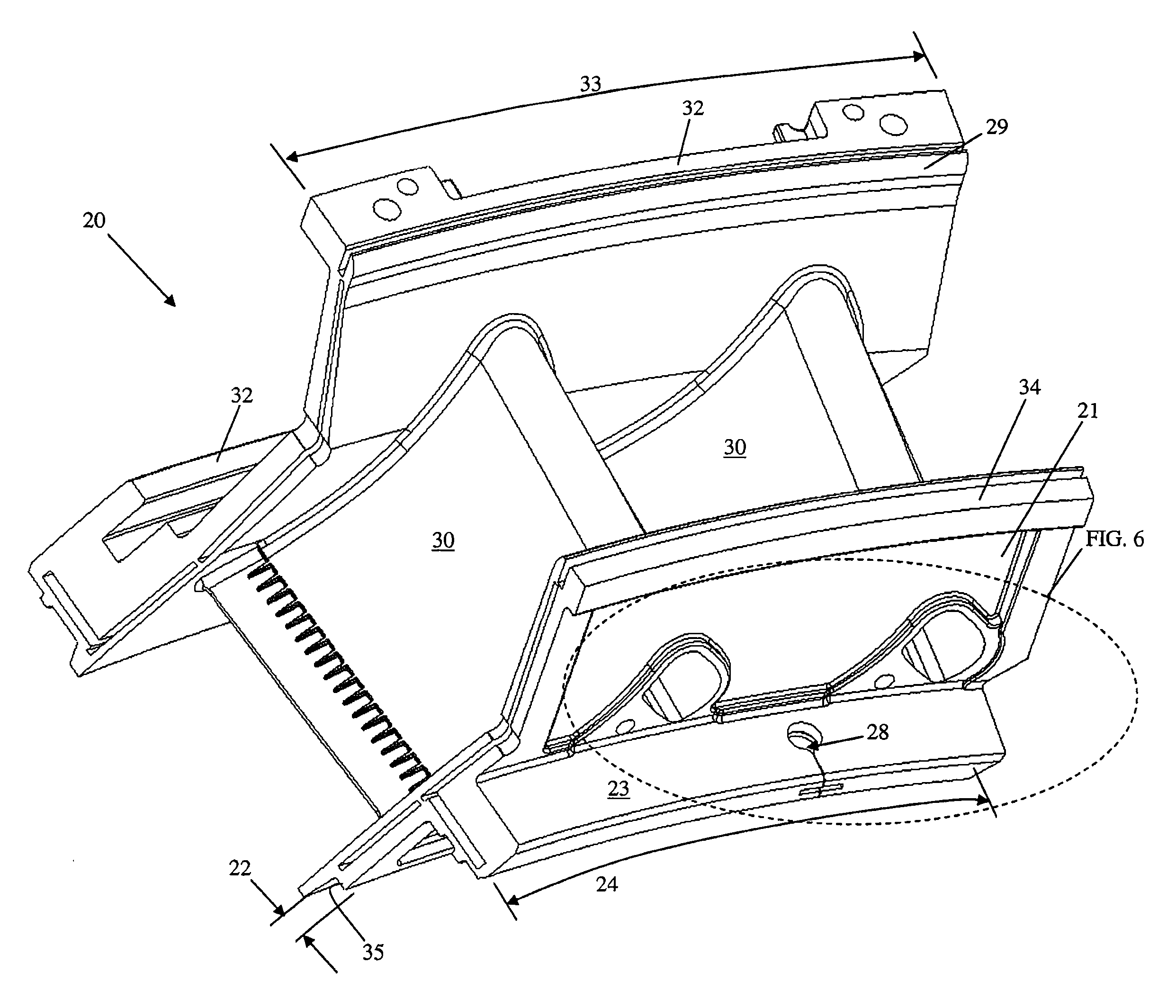
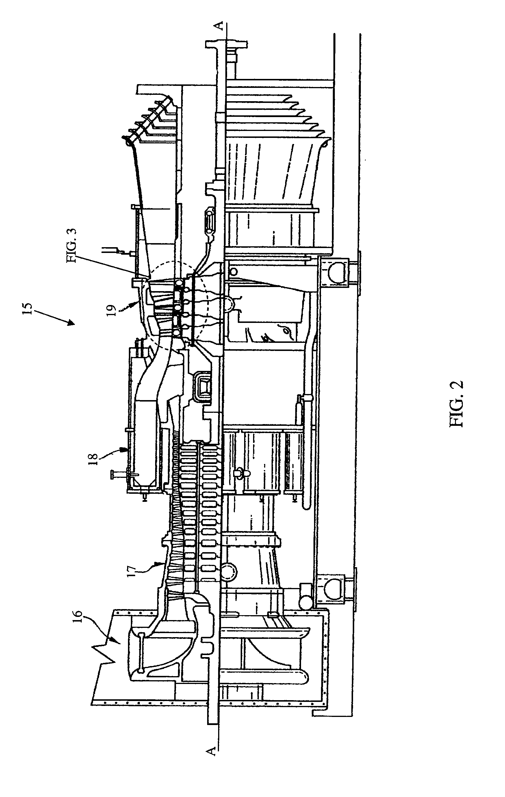
[0022] The present invention is shown in detail in FIGS. 2-7. Referring initially to FIG. 2, a partial cross section of a typical gas turbine engine 15 is shown. The engine includes an air inlet 16, a compresso...


PUM


Abstract

A vane assembly for a gas turbine engine is disclosed having lower thermally induced stresses resulting in improved component durability. The stresses in the vane assembly airfoils are lowered by increasing the flexibility of the vane platform and reducing its resistance to thermal deflection. This is accomplished by placing an opening along the innermost vane assembly rail that reduces the effective stiffness of the platform, thereby lowering the operating stresses in the airfoils of the vane assembly. A removable seal is then placed in the opening in order to prevent undesired leakages, while maintaining the benefit of the increased platform flexibility.

Description

CROSS-REFERENCE TO RELATED APPLICATIONS [0001] This application is a continuation-in-part of U.S. patent application Ser. No. 10 / 891,400, filed on Jul. 14, 2004, and assigned to the same assignee hereof.STATEMENT REGARDING FEDERALLY SPONSORED RESEARCH OR DEVELOPMENT [0002] Not Applicable. TECHNICAL FIELD [0003] The present invention relates generally to gas turbine engines and more specifically to a turbine vane configuration having reduced airfoil stresses. BACKGROUND OF THE INVENTION [0004] A gas turbine engine typically comprises a multi-stage compressor, which compresses air drawn into the engine to a higher pressure and temperature. A majority of this air passes to the combustors, which mix the compressed heated air with fuel and contain the resulting reaction that generates the hot combustion gases. These gases then pass through a multi-stage turbine, which, in turn drives the compressor, before exiting the engine. A portion of the compressed air from the compressor bypasses t...

Claims


Application Information

Patent Timeline
IPC IPC(8): F01D9/00
CPCF05D2260/941F01D9/041F01D11/005
Inventor ELLIS, CHARLIEPARKER, DAVIDSTROHL, J. PAGEMEDRANO, DAVID
Owner ANSALDO ENERGIA SWITZERLAND AG
Why Eureka
Try Eureka