Liner element for a turbine intermediate case

a technology of intermediate case and liner element, which is applied in the direction of engine fuction, machine/engine, engine manufacturing, etc., can solve the problems of high thermal stress in the component and large amount of material for stiffening ribs, and achieve the effect of sufficient stiffness and reduced thermal stress

Active Publication Date: 2018-02-08
MTU AERO ENGINES GMBH
View PDF0 Cites 3 Cited by
  • Summary
  • Abstract
  • Description
  • Claims
  • Application Information

AI Technical Summary

Benefits of technology

[0006]It is-an object of the present invention to provide a liner element for an annular duct of a turbine intermediate case, which liner element provides sufficient stiffness using little material and makes it possible to reduce thermally induced stresses.

Problems solved by technology

Such stiffening ribs do allow high stiffness to be achieved for the components; however, high thermal stresses are induced in the component due to the connection of the stiffening ribs to the edge portions.
Moreover, such known stiffening ribs require a large amount of material.

Method used


Image

  • Liner element for a turbine intermediate case
  • Liner element for a turbine intermediate case
  • Liner element for a turbine intermediate case

Examples


Embodiment Construction

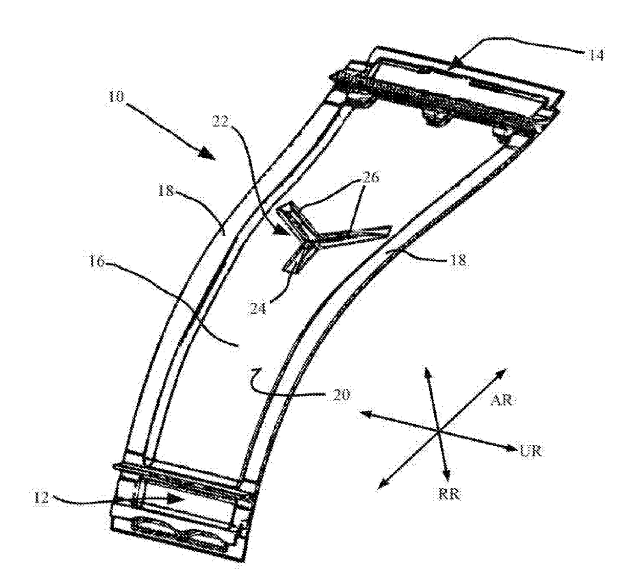
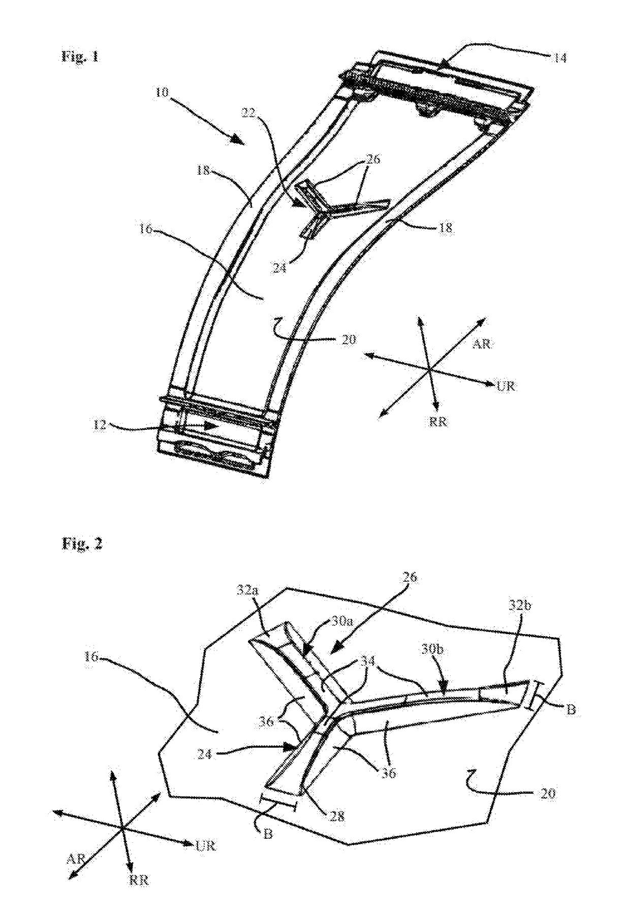
[0025]FIG. 1 shows, in simplified, schematic perspective view, a liner element 10 of a turbine intermediate case (See FIG. 5). The present example, as illustrated in FIG. 1, shows a so-called “inner duct panel;” i.e., a liner element which is adapted to radially inwardly bound the hot gas duct of the turbine intermediate case. FIG. 1 shows the surface of the liner element which faces away from the hot gas duct and which, when installed, faces radially inwardly relative to the machine axis of the gas turbine. Liner element 10 has a first, axially forward connecting portion 12 and a second, axially rearward connecting portion 14. These two connecting portions 12, 14 serve to connect liner element 10 to axially adjoining components 101, 102 of the turbine intermediate case 100 or of an associated gas turbine, as shown schematically in FIG. 5. A central portion 16 extends between first connecting portion 12 and a second connecting portion 14 along axial direction AR. In circumferential ...


PUM


Abstract

A liner element of a hot-gas-conveying duct of a turbine intermediate case of a gas turbine, in particular of an aircraft gas turbine, the liner element includes a central portion having at least one first reinforcement portion projecting in a direction away from the duct and extending substantially straight between an axial forward end and an axial rearward end; at least one of the two axial ends being adjoined by a second reinforcement portion projecting in a direction away from the duct and extending inclinedly or curvedly relative to the straight-line extent of the first reinforcement portion; the first reinforcement portion and the second reinforcement portion together forming a reinforcing element; the entire reinforcing element being disposed within the outer surface of the central portion, in particular in such a way that the reinforcing element is spaced apart from the first connecting portion and from the second connecting portion.

Description

[0001]This claims the benefit of German Patent Application DE102016213810.3, filed Jul. 27, 2016 and hereby incorporated by reference herein.[0002]The present invention relates to a liner element of a hot-gas-conveying duct of a turbine intermediate case of a gas turbine, in particular of an aircraft gas turbine, the liner element including a first, axially forward connecting portion and a second, axially rearward connecting portion, a central portion connected to the first connecting portion and the second connecting portion and located axially therebetween; the central portion having an outer surface facing away from the duct; and the first connecting portion being couplable to axially forward components of the gas turbine, and the second connecting portion being couplable to axially rearward components of the gas turbine.[0003]Directional words such as “axial,”“axially,”“radial,”“radially,” and “circumferential” are taken with respect to the machine axis of the turbine intermedia...

Claims


Application Information

Patent Timeline
Patent Type & Authority Applications(United States)
IPC IPC(8): F01D25/24
CPCF01D25/24F05D2220/323F05D2240/12F05D2240/14F05D2260/941F05D2250/75F05D2260/96
Inventor FLATSCHER, THOMASEICHINGER, ALOISBICKMEIER, WOLFGANGFELDMANN, MANFREDKIRCHNER, DANIELGEISLER, JOHANNES
Owner MTU AERO ENGINES GMBH
Why Eureka
Try Eureka