Axial bearing arrangement in a hermetic compressor

Inactive Publication Date: 2007-07-19
WHIRPOOL SA
View PDF7 Cites 10 Cited by
  • Summary
  • Abstract
  • Description
  • Claims
  • Application Information

AI Technical Summary

Benefits of technology

[0012] It is a generic object of the present invention to provide a bearing arrangement in a reciprocating hermetic compressor of refrig

Problems solved by technology

In the constructions described above in relation to a sliding axial bearing, the perfect parallelism between the mutually confronting surfaces which define the axial bearing is not guaranteed due to the presence of position errors (axial strikes) and mainly deformations of the components during the compressor operation.
These errors and deformations give rise to a geometry which is unfavorable to the for

Method used


Image

  • Axial bearing arrangement in a hermetic compressor
  • Axial bearing arrangement in a hermetic compressor
  • Axial bearing arrangement in a hermetic compressor

Examples


Embodiment Construction

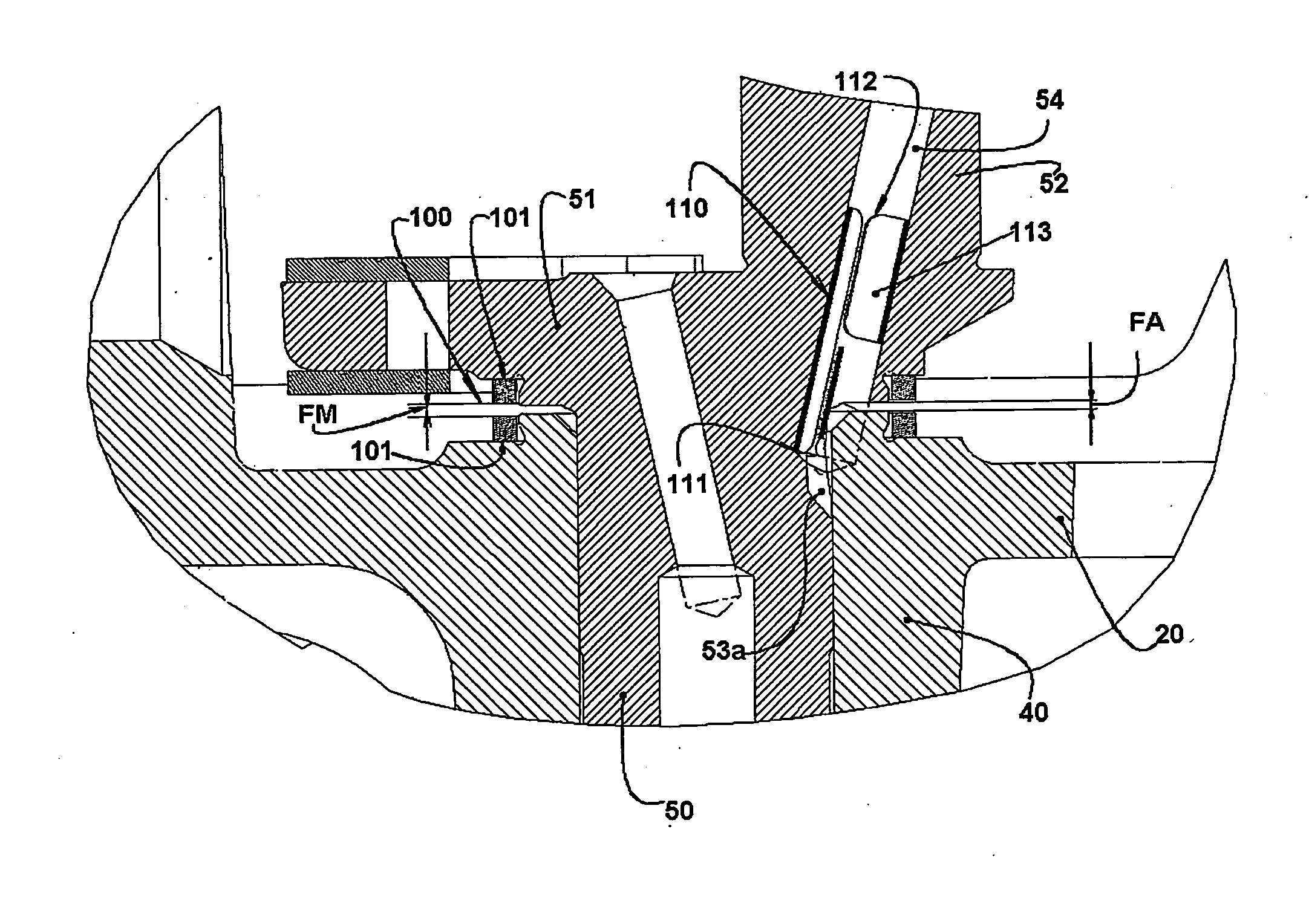
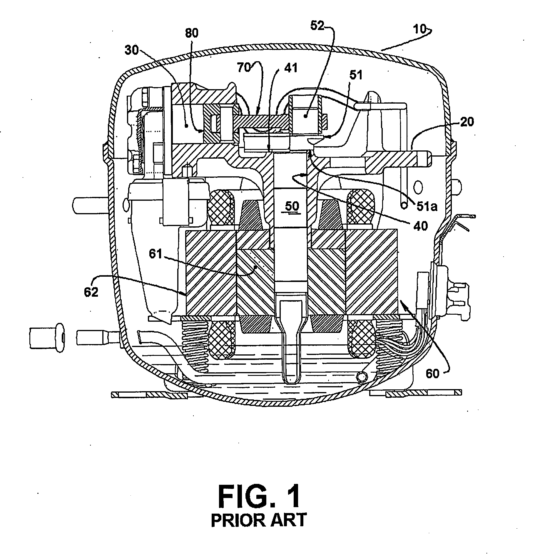
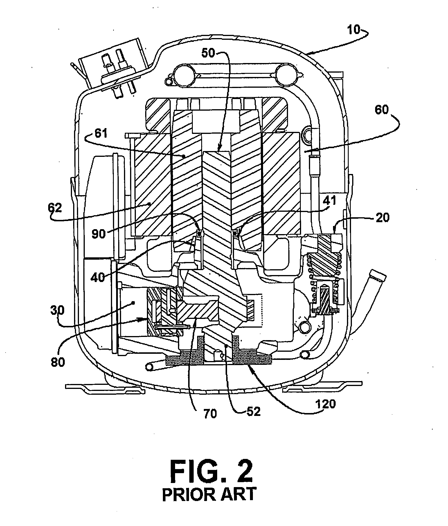
[0024]FIG. 1 illustrates, in a simplified way, a reciprocating hermetic compressor comprising a shell 10 within which is appropriately suspended a cylinder block 20, defining a cylinder 30 and incorporating a radial vertically disposed bearing hub 40 rotatively supporting a vertical crankshaft 50, having a first end portion projecting outwardly from the radial bearing hub 40 so as to secure a rotor 61 of an electric motor 60, whose stator 62 is secured under a cylinder block 20. The crankshaft 50 further presents a second end portion projecting outwardly from the radial bearing hub 40 and incorporating a peripheral flange 51, whose lower face defines an axial bearing annular surface 51a and an eccentric portion 52 to which is mounted the larger eye of a connecting rod 70, whose smaller eye is mounted to a piston 80 reciprocating inside the cylinder 30.

[0025] In this type of prior art construction, the axial bearing annular surface 51a is seated on an upper annular face 41 of the ra...


PUM


Abstract

A magnetic axial bearing arrangement in a reciprocating hermetic compressor, comprising: a cylinder block (20) and a radial bearing hub (40); a crankshaft (50) securing a rotor (61) of an electric motor (60), said arrangement comprising at least one magnetic axial bearing assembly (100) formed of a pair of magnet elements (101), a magnet element (101) of each pair being mounted to a respective part of at least one of the pairs of parts of crankshaft (50) and cylinder block (20), of cylinder block (20) and rotor (61), or of crankshaft (50) and external bearing (120), the parts of at least one of the pairs of parts carrying respective confronting mechanical stops which are maintained spaced apart by an axial gap (FA) smaller than a magnetic axial gap (FM) higher than zero and to be maintained between the magnet elements (101) of a magnetic axial bearing assembly (100).

Description

FIELD OF THE INVENTION [0001] The present invention refers to an axial bearing arrangement in a reciprocating hermetic compressor with vertical shaft of the type used in small refrigeration systems. BACKGROUND OF THE ART [0002] Hermetic compressors of refrigeration present, mounted inside a hermetically sealed shell a cylinder block, supporting a vertical crankshaft to which is mounted the rotor of an electric motor. The weight of the crankshaft-rotor assembly is supported by an axial bearing, generally in the form of a flat sliding axial bearing in which an oil film guarantees the separation of the surfaces with mutual relative movement (slipping), or in the form of a roller bearing (U.S. Pat. No. 4,632,644; WO03 / 019008) in which a ball assembly supports the axial weight, rolling on races that resist the Hertz tensions developed by contact with the balls. [0003] The crankshaft carries, in its lower end, a pump rotor, which during the operation of the compressor conducts lubricant o...

Claims


Application Information

Patent Timeline
IPC IPC(8): F04B17/00F04B39/00F04B39/02F16C39/06
CPCF04B39/0094F16C39/063F04B39/0246F04B39/023F04B39/02F16C39/00
Inventor MANKE, ADILSON LUIZDOKONAL, LUIZ VON
Owner WHIRPOOL SA
Why Eureka
Try Eureka