Stamper, method of forming a concave/convex pattern, and method of manufacturing an information recording medium

a technology of concave/convex pattern and manufacturing method, which is applied in the direction of photomechanical equipment, instruments, originals for photomechanical treatment, etc., can solve the problems of concave/convex pattern transfer risk, concave/convex pattern transfer defect risk, and high pressure applied to the resin layer, so as to avoid deformation and transfer defect risk, the effect of excessive pressur

Inactive Publication Date: 2007-07-19
TDK CORPARATION
View PDF15 Cites 15 Cited by
  • Summary
  • Abstract
  • Description
  • Claims
  • Application Information

AI Technical Summary

Benefits of technology

[0007]On the other hand, in the method of forming the concave / convex pattern disclosed by Japanese Laid-Open Patent Publication No. 2003-157520, imprinting is carried out with an elastic body present between the stamper and the press and / or between the base plate to be transferred (substrate) and the press. When doing so, by sandwiching an elastic body between the stamper and the press, for example, as described earlier it is possible to correct tilting of the stamper with respect to the substrate by causing the elastic body to deform when the stamper is pressed onto the resin layer. However, in this method of forming a concave / convex pattern, when imprinting is carried out with an elastic body present between the stamper and the press, for example, the pressure applied to the surface of the resin layer will be lower at an area where an end area (i.e., outer edge area) of the elastic body and the stamper coincide compared to an area located further inside than such area. This results in a situation where the concave / convex pattern is insufficiently pressed into the resin layer at the area where the end area of the elastic body and the stamper coincide (i.e., transfer defects occur in the concave / convex pattern).
[0008]The present inventors found that when imprinting is carried out with an elastic body with a diameter that is equal to or larger than that of the stamper and / or the substrate sandwiched as described above, a phenomenon occurs where there is a difference in the pressure applied to the surface of the resin layer between the outer edge area of the stamper (i.e., the area where the outer edge area of the stamper and the elastic body coincide) and an inner area located further inside than the outer edge area of the stamper. More specifically, when imprinting is carried out with an elastic body with a diameter that is equal to or larger than that of the stamper and / or the substrate provided between the stamper and the press, for example, the pressure applied to the surface of the resin layer is lower in the outer edge area of the stamper compared to the inner area. As a result, the concave / convex pattern is insufficiently pressed into the resin layer in the outer edge area of the stamper, resulting in transfer defects being produced in the concave / convex pattern. On the other hand, if, to avoid the occurrence of transfer defects in the concave / convex pattern, the pressing force applied to the stamper is increased so that sufficient pressure is applied in an area where the end area of the elastic body and the stamper coincide (the case where the elastic body has a smaller diameter than the stamper) or in an area where the outer edge area of the stamper and the elastic body coincide (the case where the elastic body has a diameter that is not smaller than the diameter of the stamper), the pressure applied to the resin layer will become excessively high in an area located further inside than such area (for example, an area that is located further inside than the end area of the elastic body), resulting in the risk of deformation occurring in the concave / convex pattern transferred to the resin layer. Also, if a center hole is present in any of the stamper and the substrate, when a concave / convex pattern is formed in a resin layer according to the method of forming the concave / convex pattern disclosed by Japanese Laid-Open Patent Publication No. 2003-157520, the pressure applied to the surface of the resin layer is lower in the rim area of the center hole compared to an area located further outside than the rim area. In this way, according to the method of forming the concave / convex pattern disclosed by Japanese Laid-Open Patent Publication No. 2003-157520, there is the risk of deformation and / or transfer defects in the concave / convex pattern due to the difference in pressure applied to the surface of the resin layer at different positions on the stamper.
[0009]The present invention was conceived in view of the problems described above and it is a principal object of the present invention to provide a stamper, a method of forming a concave / convex pattern, and a method of manufacturing an information recording medium that can avoid deformation and transfer defects in a concave / convex pattern.

Problems solved by technology

However, by investigating these conventional methods of forming a concave / convex pattern, the present inventors found the following problems.
As a result, due to the excessively high pressure applied to the resin layer at the outer edge area, there is the risk of deformation occurring in the concave / convex pattern transferred to the resin layer.
Also, when the pressing force applied to the stamper is lowered to only the force that is required at the outer edge area to avoid deformation of the concave / convex pattern, a situation is produced where in the inner area where the pressure applied to the surface of the resin layer is lower compared to the outer edge area, the concave / convex pattern is insufficiently pressed into the resin layer, resulting in the occurrence of transfer defects in the concave / convex pattern.
In this way, with the method of forming a concave / convex pattern disclosed by U.S. Pat. No. 5,772,905, there is the risk of deformation and / or transfer defects in the concave / convex pattern due to the difference in the pressure applied to the surface of the resin layer between the outer edge area and the inner area of the stamper.
This results in a situation where the concave / convex pattern is insufficiently pressed into the resin layer at the area where the end area of the elastic body and the stamper coincide (i.e., transfer defects occur in the concave / convex pattern).
As a result, the concave / convex pattern is insufficiently pressed into the resin layer in the outer edge area of the stamper, resulting in transfer defects being produced in the concave / convex pattern.
On the other hand, if, to avoid the occurrence of transfer defects in the concave / convex pattern, the pressing force applied to the stamper is increased so that sufficient pressure is applied in an area where the end area of the elastic body and the stamper coincide (the case where the elastic body has a smaller diameter than the stamper) or in an area where the outer edge area of the stamper and the elastic body coincide (the case where the elastic body has a diameter that is not smaller than the diameter of the stamper), the pressure applied to the resin layer will become excessively high in an area located further inside than such area (for example, an area that is located further inside than the end area of the elastic body), resulting in the risk of deformation occurring in the concave / convex pattern transferred to the resin layer.
In this way, according to the method of forming the concave / convex pattern disclosed by Japanese Laid-Open Patent Publication No. 2003-157520, there is the risk of deformation and / or transfer defects in the concave / convex pattern due to the difference in pressure applied to the surface of the resin layer at different positions on the stamper.

Method used


Image

  • Stamper, method of forming a concave/convex pattern, and method of manufacturing an information recording medium
  • Stamper, method of forming a concave/convex pattern, and method of manufacturing an information recording medium
  • Stamper, method of forming a concave/convex pattern, and method of manufacturing an information recording medium

Examples


Embodiment Construction

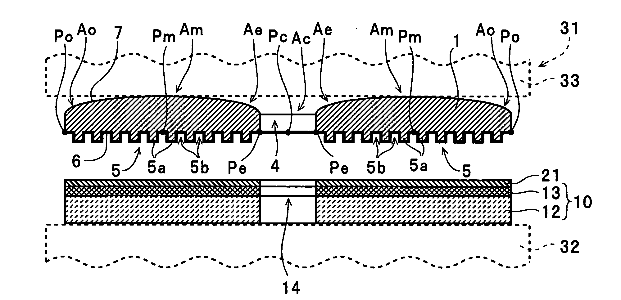
[0052]Preferred embodiments of a stamper, a method of forming a concave / convex pattern, and a method of manufacturing an information recording medium according to the present invention will now be described with reference to the attached drawings.

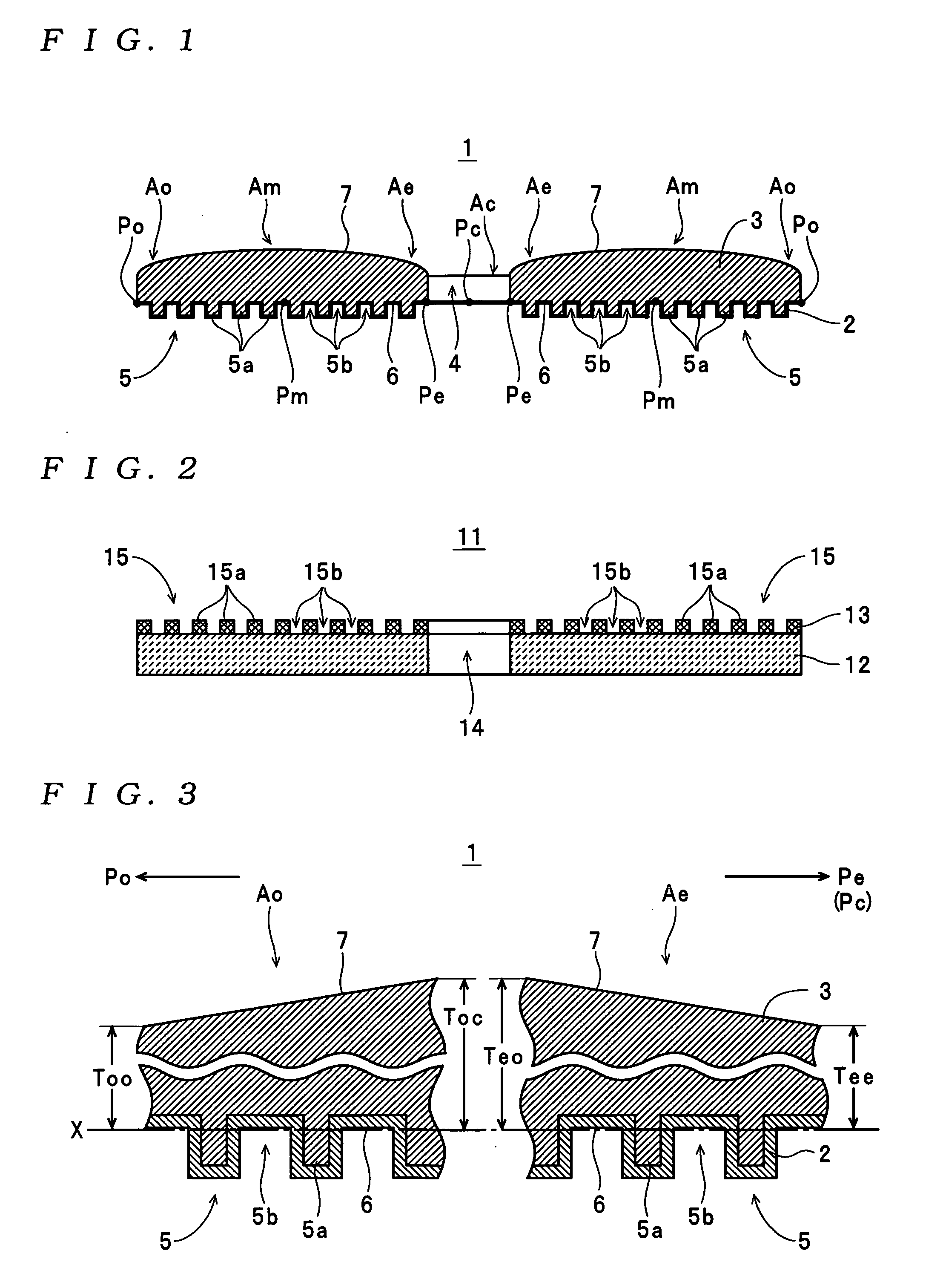
[0053]The construction of a stamper 1 that is one example of a stamper according to the present invention will now be described with reference to the drawings.

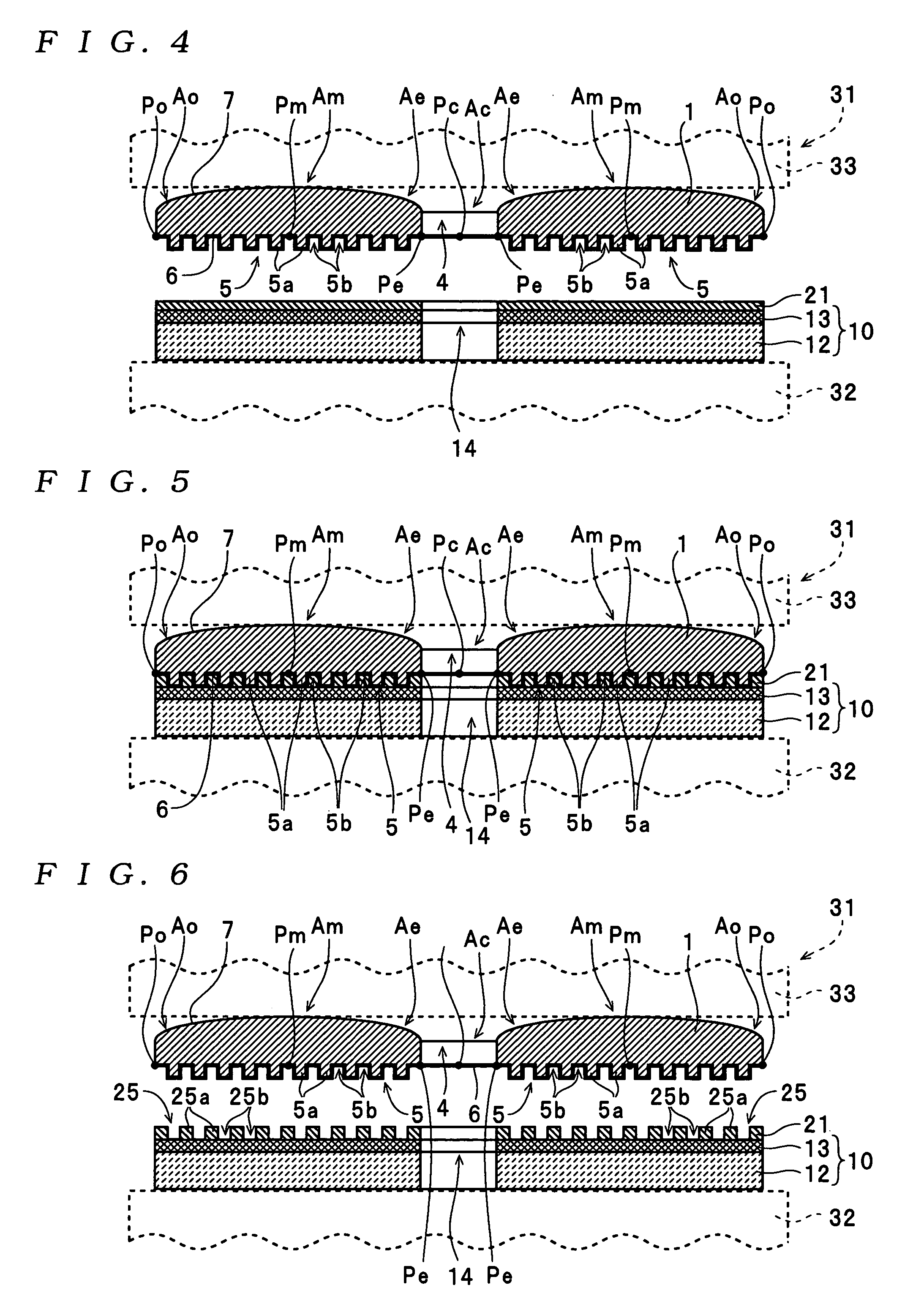
[0054]The stamper 1 shown in FIG. 1 is a matrix for manufacturing a magnetic disk 11 (one example of an “information recording medium” for the present invention) shown in FIG. 2 in accordance with a method of manufacturing an information recording medium according to the present invention, and is formed in an overall circular plate-like shape. Here, the magnetic disk 11 is a discrete track-type magnetic recording medium (a “patterned medium”) on which data can be recorded by perpendicular recording, for example. As shown in FIG. 2, a recording layer (a magnetic recording layer) 13 is ...


PUM

PropertyMeasurementUnit
thicknessaaaaaaaaaa
thicknessaaaaaaaaaa
sizeaaaaaaaaaa

Abstract

A stamper is formed so that a thickness between a concave/convex pattern formation surface, where a concave/convex pattern is formed, and a rear surface gradually decreases in a predetermined area of the stamper. The predetermined area corresponds to an area where pressure is likely to be concentrated when the concave/convex pattern of the stamper is used to form a concave/convex pattern on a substrate. A method of forming a concave/convex pattern uses such stamper, and a method of manufacturing an information recording medium uses a concave/convex pattern formed by such method.

Description

BACKGROUND OF THE INVENTION[0001]1. Field of the Invention[0002]The present invention relates to a stamper used to form a concave / convex pattern by imprinting, a method of forming a concave / convex pattern on a substrate using such stamper, and a method of manufacturing an information recording medium using a concave / convex pattern formed according to such method.[0003]2. Description of the Related Art[0004]As one example of a method of forming a concave / convex pattern using this type of stamper, the specification of U.S. Pat. No. 5,772,905 discloses a nano-imprint lithography method (i.e., a method of forming a concave / convex pattern of nanometer size: hereinafter simply “imprinting method”) that forms a concave / convex pattern of nanometer size on a substrate by pressing a stamper (“mold”) on which a concave / convex pattern of nanometer size has been formed onto a resin layer on a substrate to transfer the concave / convex pattern of the stamper to the resin layer. In this method of fo...

Claims


Application Information

Patent Timeline
Patent Type & Authority Applications(United States)
IPC IPC(8): B29D17/00G03C5/00
CPCB29C33/424B29C43/021B29C43/361B29C2033/426G11B7/263B29C2043/3655B29C2043/5858B29D17/005G11B5/855B29C2043/025
Inventor FUJITA, MINORUHIBI, MIKIHARU
Owner TDK CORPARATION
Why Eureka
Try Eureka