
Air handling system for clean room

a technology for air handling and clean rooms, applied in space heating and ventilation, lighting and heating apparatus, heating types, etc., can solve the problems of inefficiency, general proportional contamination level of clean air, and level of clean spa

Active Publication Date: 2007-07-19
GHATTAS RAY
View PDF18 Cites 34 Cited by
  • Summary
  • Abstract
  • Description
  • Claims
  • Application Information

AI Technical Summary

Problems solved by technology

Further, the contamination level of clean air is generally proportional to the number of air changes per hour that is caused to move through the space.
More particularly, the contamination level of clean space is generally proportional to the number of filtered air changes per hour that is caused to move through the space, which may also be correlated with energy usage.
The higher the air exchange rate the cleaner the room, and the larger the quantity of in-line components required, each of which introduces its own sources of inefficiencies.
The rising cost of energy related to clean room operations has reached critical cost levels.
An important aspect of increased costs is the seemingly never-ending increase in energy costs necessary to operate at desired filtration standards in a cost-effective manner.
However, turbulent distribution of air requires a greater number of air changes to achieve a given level of efficiency, wasting energy with resulting increases in energy usage and costs.
Further, the costs of operating certain clean room elements, such as cooling coils, also directly and negatively impacts operational costs.
Specifically, it is known that the related art commonly provides for the installation of a cooling coil in tandem with each supply fan, and operation of each such cooling coil necessarily adds to the heat load to be cooled, as well as including substantial costs related to unit costs for cooling coils and related hardware associated with each supply fan / cooling coil combination.
Further, in such combination, an output airflow from each supply fan / cooling coil combination is now measurably hotter than the input airflow due to the heat output related to each additional cooling coil, which in turn must be compensated for by upsizing the entire system, also further negatively effecting operating efficiencies.
By way of example, it is known that cooling coils are designed with a restriction in air velocity therethrough which generally cannot be designed in excess of 500 feet / minute, in turn requiring a significant increase in the size of the fan and the fan box to support an increased cooling air flow, thereby further introducing additional size, weight, cost, and installation considerations and impediments.

Method used


Image

  • Air handling system for clean room
  • Air handling system for clean room
  • Air handling system for clean room

Examples


Embodiment Construction

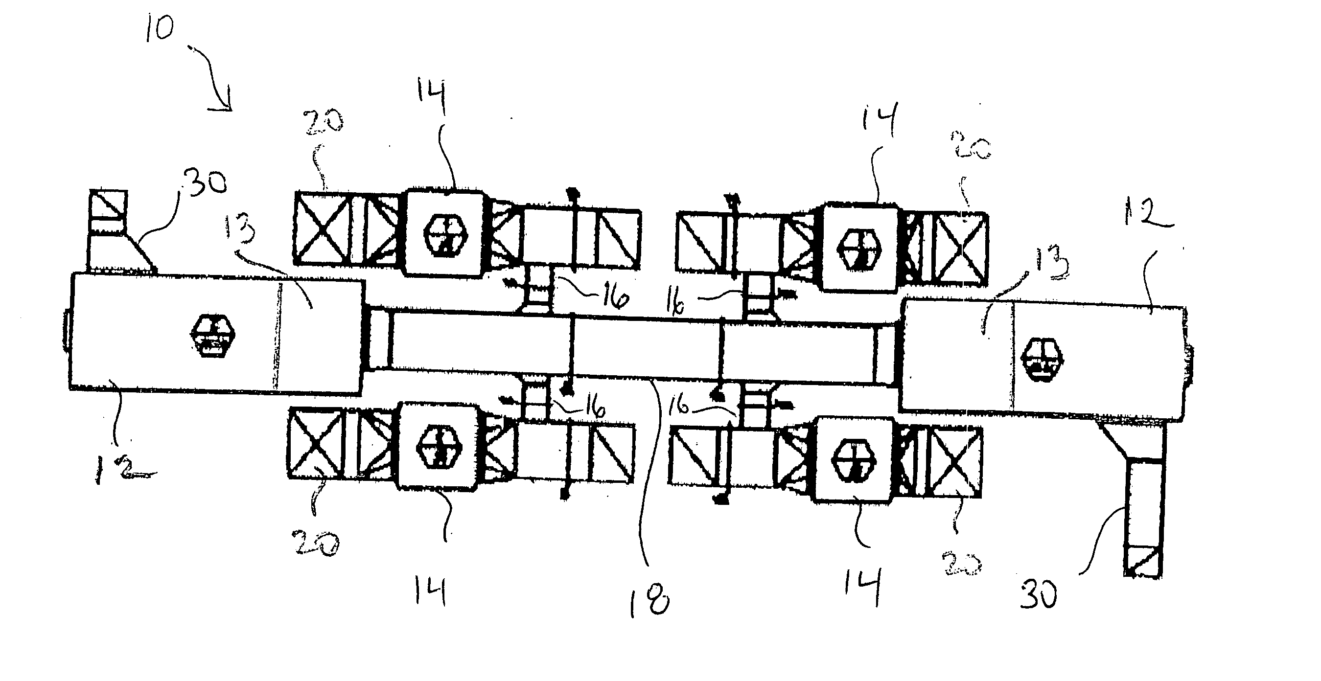
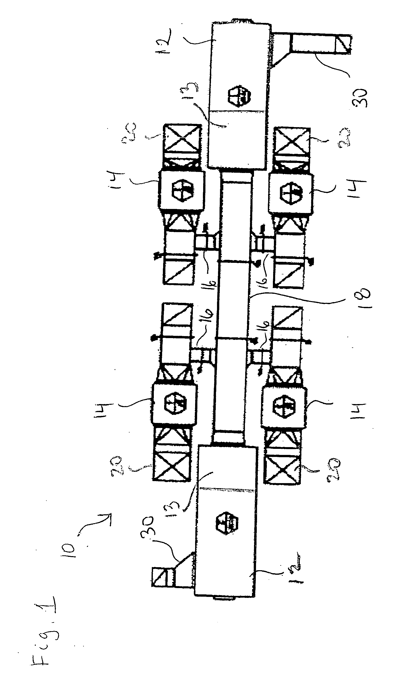
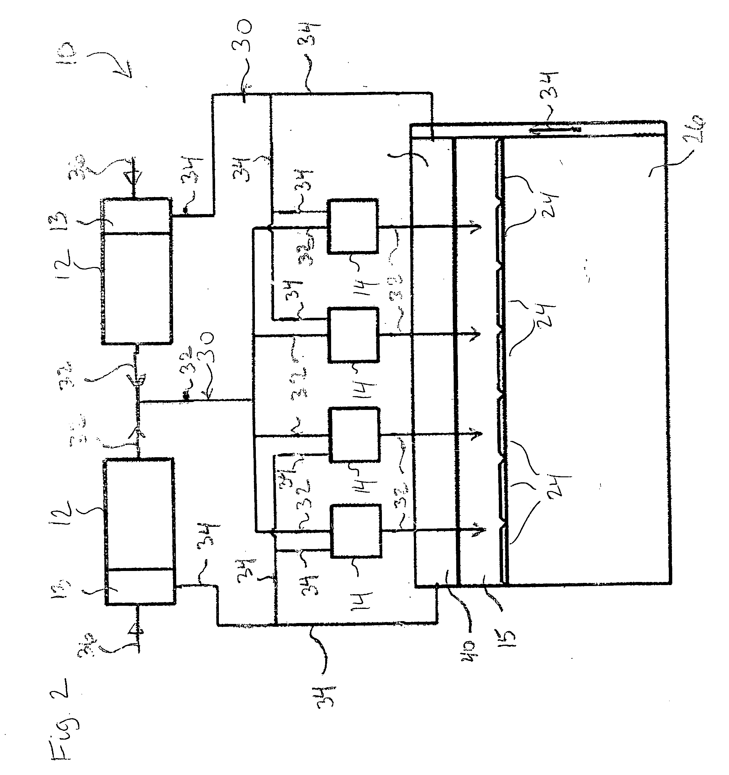
[0014] Referring to the drawings, the present invention is shown schematically in FIG. 1. In general, the inventive air handling system 10 for a clean room uses two air handling units 12 for handling an air flow. Each air handling unit 12 includes a makeup air handling unit (MAU) having a cooling unit 13 for providing desired conditioned air, including meeting specified parameters such as heating, airflow, and humidity characteristics, including temperature and relative humidity. A heating unit may be provided in connection with the MAU to also meet these requirements. As will be appreciated, return, relief, and exhaust systems provide the network that moves the air delivered by the supply distribution system back to the air handling units 12. The air is then re-circulated or exhausted out of the building as required for ventilation purposes, building pressure control purposes, or to control contamination from processes as is desired in the clean room environment.

[0015] In the pres...


PUM


Abstract

A clean room air handling system is disclosed. The system includes an air handler adapted to receive an air flow, the air handler further provided with a cooling apparatus, and at least one supply fan for generating the air flow without a cooling apparatus directly associated therewith, and modulation means for operating said system.

Description

CROSS-REFERENCE TO RELATED APPLICATIONS [0001] This application claims the benefit of the filing date of the following U.S. provisional patent application: No. 60 / 766,441, filed Jan. 19, 2006.STATEMENT RE: FEDERALLY SPONSORED RESEARCH / DEVELOPMENT [0002] not applicable BACKGROUND OF THE INVENTION [0003] 1. Field of the Invention [0004] The present invention relates generally to air delivery systems in clean rooms and, more particularly, to an air handling system for use in clean rooms applications where large volumes of particulate free, temperature and humidity controlled airflow are required. [0005] 2. Description of the Related Art [0006] Many enterprises, such as scientific laboratories, micro-electronic manufacturers, testing labs, hospitals, and the like, require relatively clean air from which substantially all dust particles, micro-organisms, and pathogens have been removed. Further, the advent of high technology developments in aerospace, electronics, optics, telecommunicati...

Claims


Application Information

Patent Timeline
IPC IPC(8): B01L1/04
CPCF24F3/161F24F3/0442F24F3/167
Inventor GHATTAS, RAY
Owner GHATTAS RAY
Learn More