Device and method for testing and for diagnosing digital circuits

a digital circuit and device technology, applied in the field of apparatus and to a method for testing and diagnosing digital circuits, can solve the problems of increasing the cost of testing and diagnosing such circuits, requiring a large amount of storage space, and taking a long tim

Inactive Publication Date: 2007-07-19
INFINEON TECH AG
View PDF14 Cites 22 Cited by
  • Summary
  • Abstract
  • Description
  • Claims
  • Application Information

AI Technical Summary

Benefits of technology

[0009] The present invention provides a test apparatus with a compactor which enables errors to be located from test responses of an electrical...

Problems solved by technology

Due to the increasing degree of integration of electrical circuits and because of the errors occurring during production and in service, the expenditure for testing and diagnosing such circuits is also increasing.
This takes a long time and requires a larg...

Method used


Image

  • Device and method for testing and for diagnosing digital circuits
  • Device and method for testing and for diagnosing digital circuits
  • Device and method for testing and for diagnosing digital circuits

Examples


Embodiment Construction

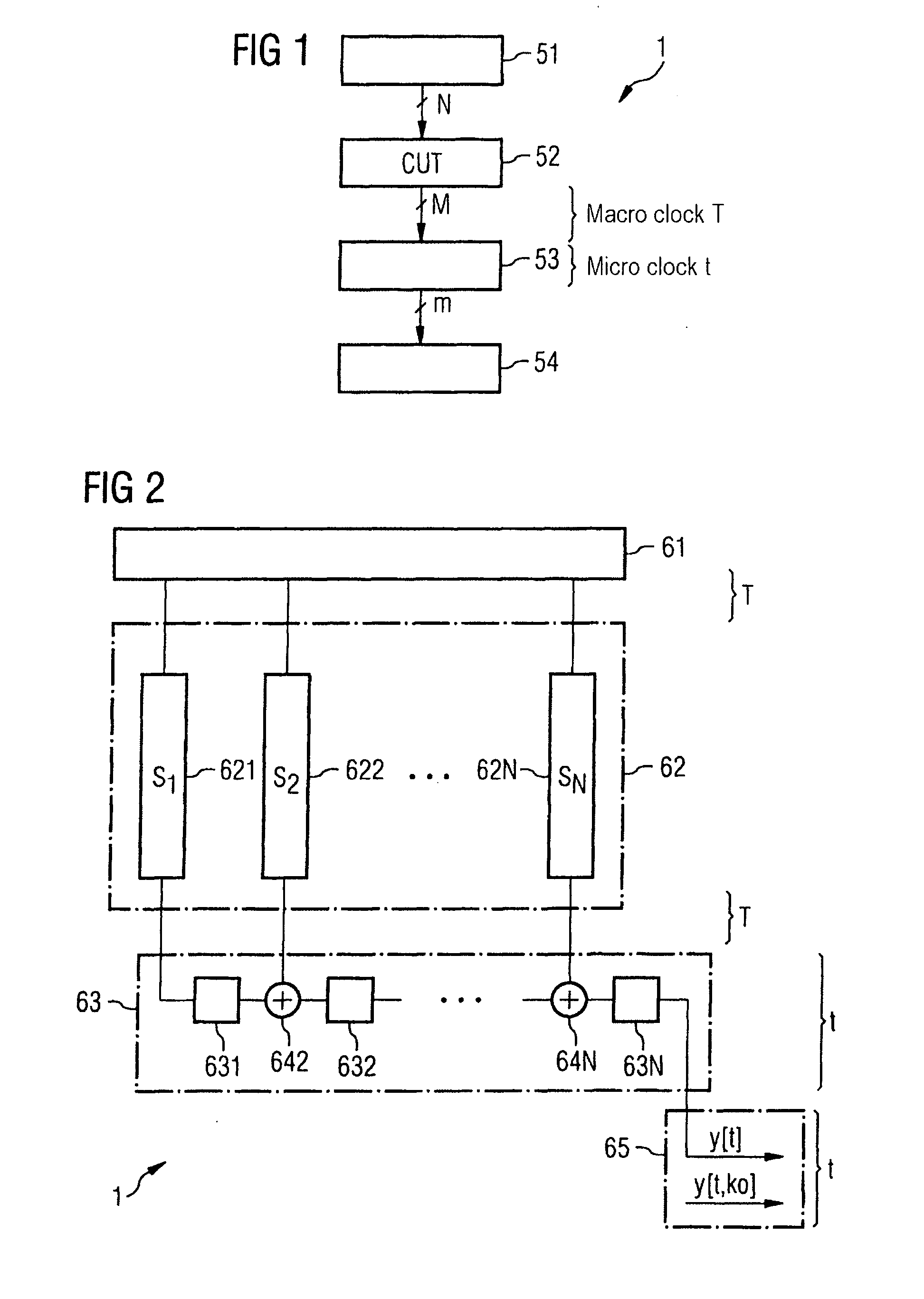
[0056]FIG. 1 shows a basic configuration of a test apparatus according to the invention for testing and for diagnosing a circuit to be tested or to be diagnosed. The test apparatus 1 includes a test input signal generator (TIG) 51, a circuit 52 to be tested or to be diagnosed, a compactor 53 and an evaluating device 54.

[0057] In this configuration, the TIG 51 can be implemented by an external tester or by a circuit on the chip. The test input signal generator 51 provides the test input signals of word width N and inputs them into the circuit 52 to be tested or to be diagnosed, also called CUT 52.

[0058] The CUT 52 outputs the test and diagnostic responses of word width M in the test and diagnostic clock cycle T. The test and diagnostic clock cycle T is also called macro clock cycle.

[0059] The test and diagnostic data output by the CUT 52 in the macro clock cycles T are compacted by the compactor 53 in a faster micro clock cycle t to form a signal of word width m, a macro clock cyc...


PUM


Abstract

A test apparatus includes a test input signal generator that generates a test input signal of word width N, and terminals that connect to inputs and outputs of an electrical circuit to be tested. The electrical circuit includes N digital test inputs and M digital test outputs. The terminals for the test inputs are connected to the test input signal and an electrical circuit is driven such that it outputs at its test outputs data with a macro clock cycle T of length L as test response. A compactor includes M inputs that are connected to the terminals for the test outputs of the circuit to be tested. The compactor compacts the test response with a micro clock cycle t of length l and outputs a data word of width m, where the length L is at least twice as large as the length l.

Description

CROSS REFERENCE TO RELATED APPLICATIONS [0001] This application claims priority under 35 USC §119 to German Application No. DE 102005046588.9, filed on Sep. 28, 2005, and titled “Device and Method for Testing and For Diagnosing Digital Circuits,” the entire contents of which are hereby incorporated by reference. Field of the Invention [0002] The invention relates to an apparatus and to a method for testing and for diagnosing digital circuits. BACKGROUND [0003] Due to the increasing degree of integration of electrical circuits and because of the errors occurring during production and in service, the expenditure for testing and diagnosing such circuits is also increasing. Complex circuits are frequently diagnosed and tested by using scan paths. In this context, the outputs of the electrical circuits also form the outputs of the scan paths. In circuits which have many outputs, there is usually a correspondingly large amount of output data which must be processed in the test. This takes...

Claims


Application Information

Patent Timeline
IPC IPC(8): G01R31/28G06F11/00
CPCG01R31/31922G11C29/40G01R31/31937G01R31/31928
Inventor LEININGER, ANDREASGOESSEL, MICHAEL
Owner INFINEON TECH AG
Why Eureka
Try Eureka