
Method and system for dynamic stochastic optimal electric power flow control

a power flow control and stochastic optimal technology, applied in the direction of electric variable regulation, process and machine control, instruments, etc., can solve the problems of large amount of wind curtailment, unanswered challenging questions, and the inability to reliably and efficiently operate a power system in such an environment, so as to improve the stability of an electrical grid, maximize the system stability margin of said electrical grid, and minimize the control effort in the electrical grid

Active Publication Date: 2016-11-29
CLEMSON UNIVERSITY +2
View PDF10 Cites 16 Cited by
  • Summary
  • Abstract
  • Description
  • Claims
  • Application Information

AI Technical Summary

Benefits of technology

[0024]In this manner, the advantages of the invention become apparent. The invention provides optimal coordinated secondary active and reactive power flow control. An analytical model of a power system is not necessary. Different performance indices and constraints of a power system can be formulated into the control objective. The invention handles power system dynamic and stochastic events by optimally and dynamically redistributing AC power flow. And the invention allows seamless integration of intermittent renewable generation resources. This will be of growing importance as the amount of energy generated from wind and solar keeps growing.
[0031]In various embodiments of the invention one of the area control error, system-wide voltage deviation, loading of system-wide heavily loaded power lines, curtailment of renewable energy generation, total fuel usage and cost, total line losses, and the control effort in said electrical grid is minimized. In other embodiments the system stability margin of said electrical grid is maximized.
[0033]The invention further provides a method of improving the stability of an electrical grid, said method comprising the steps of: receiving condition data from a multiplicity of sensors in communication with an electrical grid, wherein said multiplicity of sensors monitor conditions within said electrical grid and produce condition data corresponding to said conditions within said electrical grid; inputting said condition data into a dynamic stochastic optimal power flow (DSOPF) control system; creating a DSOPF model for said electrical grid based upon said condition data; and generating control data corresponding to said DSOPF model to control one or more of an active power generation controller and a reactive power generation controller in communication with said electrical grid and said DSOPF control system, whereby the amount of active and reactive power in said electrical grid is controlled.
[0034]In other embodiments of this method, one or more of an active power generation controller and a reactive power generation controller in communication with said electrical grid and said DSOPF control system, whereby one or more of the area control error, system-wide voltage deviation, generator speed deviations, loading of system-wide heavily loaded power lines, curtailment of renewable energy generation, total fuel usage and cost, total line losses, and the control effort in said electrical grid is minimized. In further embodiments of this method, the system stability margin of said electrical grid is maximized.

Problems solved by technology

With the increasing penetration of intermittent renewable energy, power systems encounter more and more uncertainty and variability.
How to reliably and efficiently operate a power system in such an environment is still an unanswered challenging question.
With much lower forecasting errors for loads, the traditional power system operation is based on deterministic security-constrained commitment and dispatch processes, which tend to be conservative (using forecasts with a high probability of exceedance) when intermittent renewable generation is considered.
This conservative operation contributes to a large amount of wind curtailment, as secure operation cannot be guaranteed in real time when the actual wind power significantly exceeds the forecasts used in the scheduling and dispatching processes.
No one has yet described any detailed designs or analyses for a power system control, however, to incorporate prediction and optimization over power system stochastic disturbances.
These linear controllers cannot consider multiple control objectives and cannot ensure system security in real-time.

Method used


Image

  • Method and system for dynamic stochastic optimal electric power flow control
  • Method and system for dynamic stochastic optimal electric power flow control
  • Method and system for dynamic stochastic optimal electric power flow control

Examples


example 1

Method for Power System Secondary Control

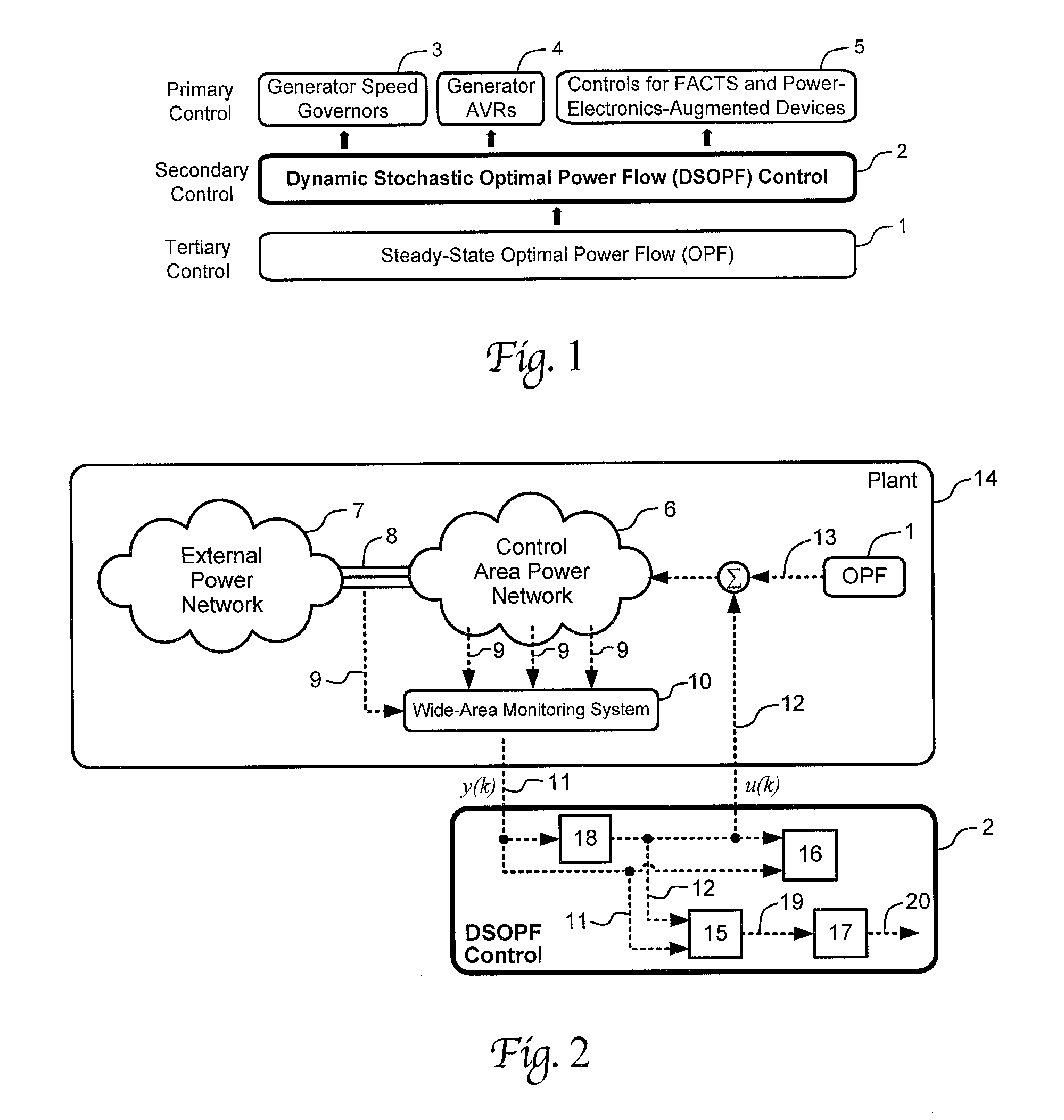
[0073]The invention includes many components and variations comprising multiple embodiments. One embodiment of the invention is a method of coordinating secondary control in a power system, namely the dynamic stochastic optimal power flow (DSOPF) control 2 as indicated in FIG. 1, which illustrates a new power system operation-control structure using a novel DSOPF control method. An existing optimal power flow (OPF) method 1 provides steady-state commands directly to local controllers, which include generator speed governors (GOV)s 3, generator automatic voltage regulators (AVRs) 4, and controls for FACTS and power-electronics-augmented devices 5. In contrast to the prior art OPF method, the DSOPF method 2 in the secondary control layer controls both the active and reactive power flows simultaneously to obtain an optimal real-time dynamic dispatch.

[0074]A generic framework of the DSOPF control 2 is illustrated in FIG. 2. The control area power...

example 2

[0103]Referring now to FIG. 12, a DSOPF is illustrated within a power system to replace the traditional linear secondary control used in most prior art grid control systems. The DSOPF controller provides nonlinear optimal control to the system-wide AC power flow using an adaptive critic design (ACD) technique. Here, “Gov's” represent governors, and “AVRs” represent automatic voltage regulators.

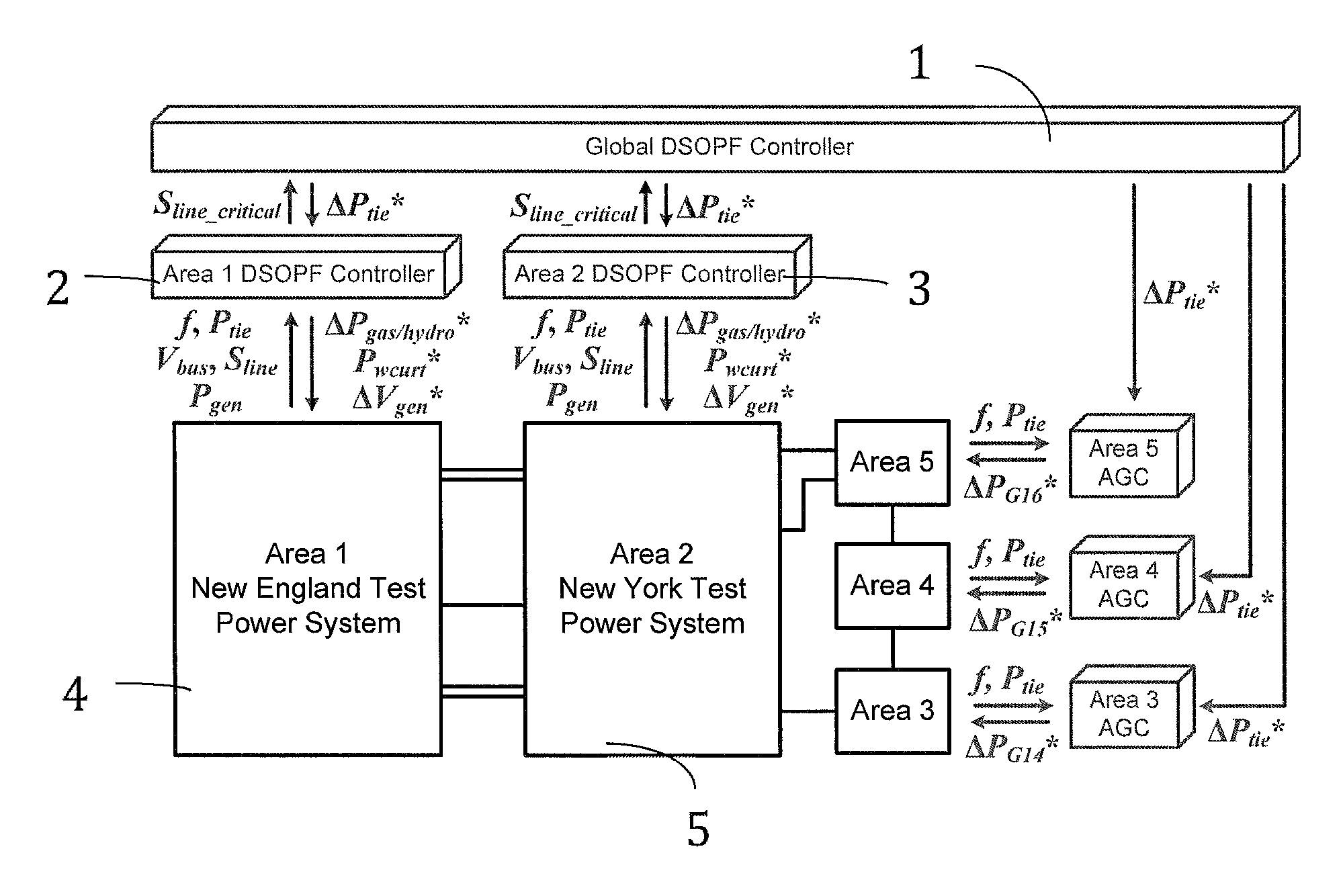
[0104]This embodiment of the invention can be illustrated in a large power system to demonstrate its effectiveness in controlling the active and reactive power flow in a traditional grid. The 70-bus system, as shown in FIG. 13, is developed from a 68-bus New England New York test power system. Area 1 with generators G1 to G9 (7650 MVA of total installed capacity) represents the New England Test System. Area 2 with generators G10 to G13 (14170 MVA of total installed capacity) represents the New York Power System. Generators G14 to G16 (10000 MVA each) are aggregated representations of three int...

case 1

Large Wind Power Variation

[0135]A large wind variation is applied to wind plants G17 and G18 starting at 300 s, as shown in FIG. 17. This example is used to study the controller performance in the presence of high wind variability.

[0136]In this example, no wind curtailment is generated from the area DSOPF controllers. With the same wind power variation, the area DSOPF controllers result in a lower overall utility than AGCs+SVCs, as shown in FIG. 18. In other words, a better overall quasi-steady-state performance is achieved by the area DSOPF controllers.

[0137]By leveraging the load-voltage characteristics, the DSOPF controllers result in less frequency variation, as shown in FIG. 19. The DSOPF controllers temporarily increase the voltage and thereby increasing load consumption, when the frequency is high. Neither the AGCs nor the SVCs can achieve this performance, since they decouple the active and reactive power control. AGCs do not control voltage, and SVCs do not respond to frequ...


PUM


Abstract

A dynamic stochastic optimal power flow (DSOPF) control system is described for performing multi-objective optimal control capability in complex electrical power systems. The DSOPF system and method replaces the traditional adaptive critic designs (ACDs) and secondary voltage control, and provides a coordinated AC power flow control solution to the smart grid operation in an environment with high short-term uncertainty and variability. The DSOPF system and method is used to provide nonlinear optimal control, where the control objective is explicitly formulated to incorporate power system economy, stability and security considerations. The system and method dynamically drives a power system to its optimal operating point by continuously adjusting the steady-state set points sent by a traditional optimal power flow algorithm.

Description

CROSS-REFERENCE TO RELATED APPLICATIONS[0001]This application claims priority to U.S. Provisional Appl. No. 61 / 621,654 filed Apr. 9, 2012, which is incorporated herein by reference.STATEMENT OF GOVERNMENT SUPPORT[0002]This invention was made with government support under grants #1238097, 1231820 and 0802047, awarded by The National Science Foundation. The U.S. Government has certain rights in this invention.FIELD OF THE INVENTION[0003]The present invention generally relates to electrical power control systems and, more particularly, to a dynamic stochastic optimal power flow (DSOPF) control system that provides multi-objective optimal control capability to complex electrical power systems. The DSOPF control may be implemented using nonlinear optimal control techniques, including but not limited to adaptive critic designs and the model predictive control method. The invention provides a coordinated secondary AC power flow control solution to electrical power systems with high penetra...

Claims


Application Information

Patent Timeline
Patent Type & Authority Patents(United States)
IPC IPC(8): G05F5/00H02J3/16
CPCG05F5/00H02J3/16
Inventor VENAYAGAMOORTHY, GANESH KUMARLIANG, JIAQIHARLEY, RONALD GORDON
Owner CLEMSON UNIVERSITY
Learn More