Gas spring for a revolver cannon or breech cannon

Inactive Publication Date: 2007-07-26
OERLIKON CONTRAVES BESCHRAENKTER HAFTUNG
View PDF18 Cites 1 Cited by
  • Summary
  • Abstract
  • Description
  • Claims
  • Application Information

AI Technical Summary

Benefits of technology

[0007] The system can be switched preferably between two different states. Thus, for example, it would be possible to adjust the springs to a softer setting during an ongoing process, e.g., during firing.
[0008] In addition, this system can support charging, where the reserve volu

Problems solved by technology

Changing the setting, especially changing the setting rapidly to deal with changes in the operating conditions associated with, for example, the effects of temperature, cannot be accomplished without com

Method used


Image

  • Gas spring for a revolver cannon or breech cannon
  • Gas spring for a revolver cannon or breech cannon

Examples


Embodiment Construction

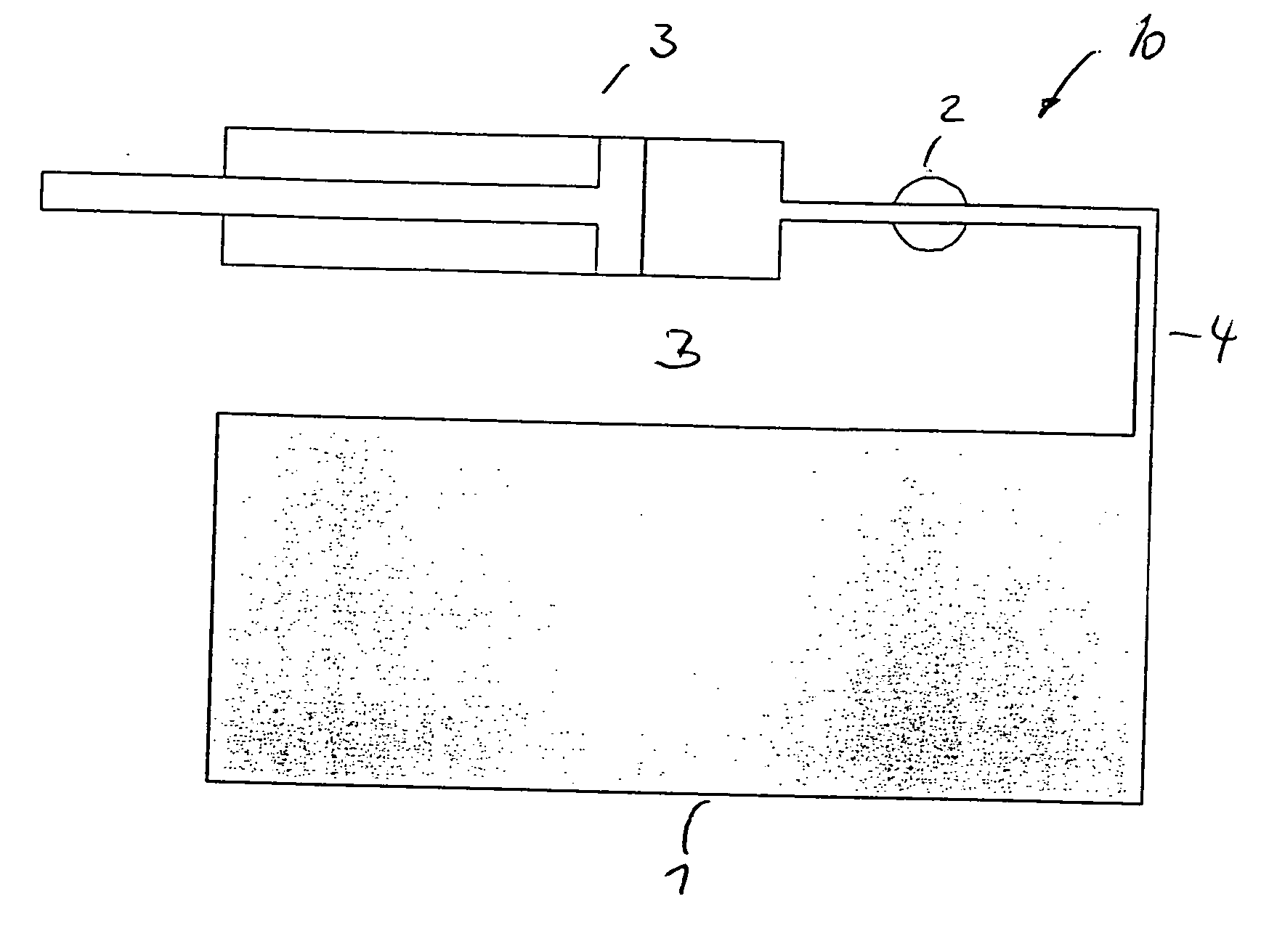
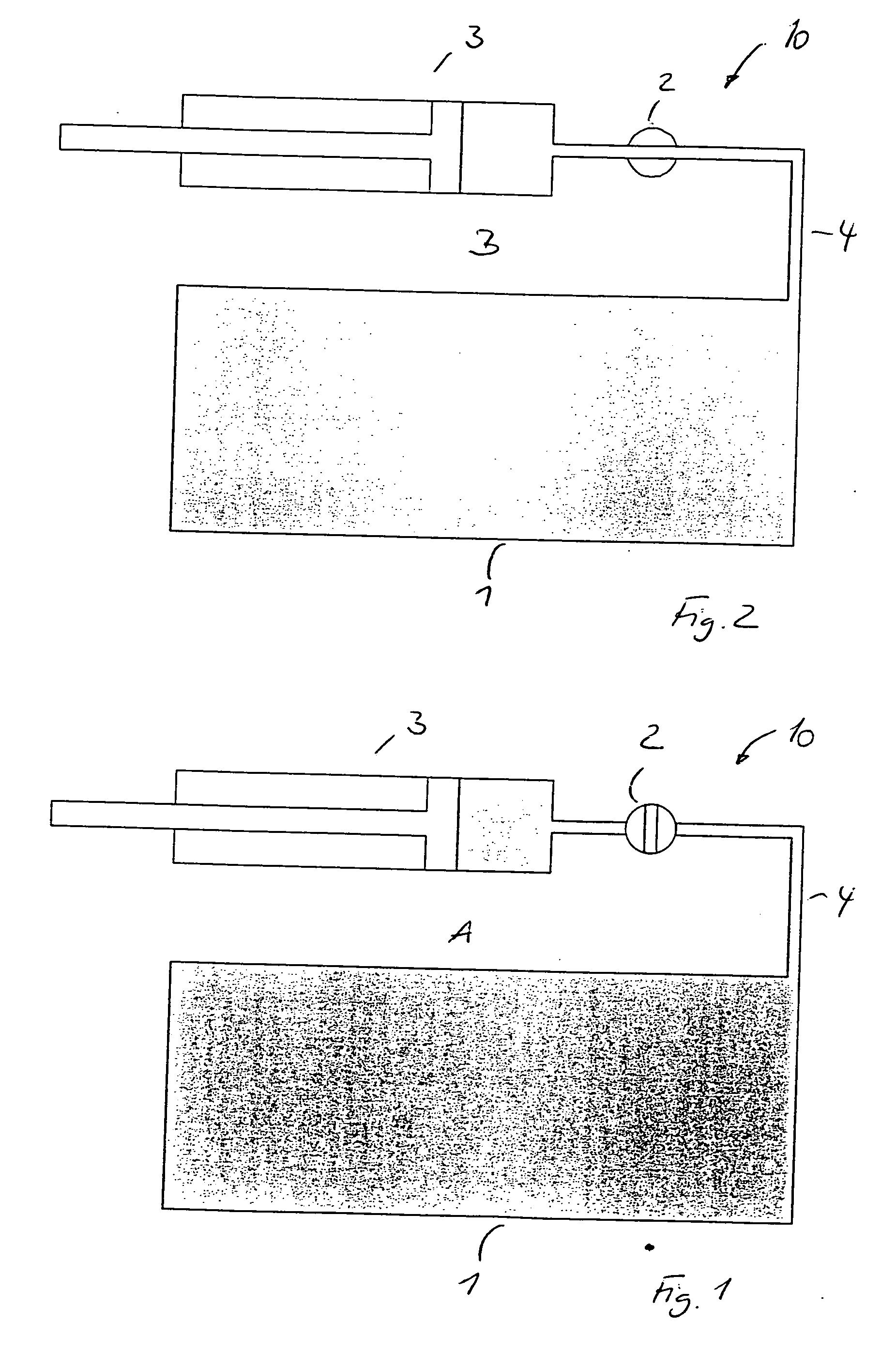
[0017]FIG. 1 and FIG. 2 show the additional gas system 10 for a gas spring 3 on the cannon side with at least one reserve tank 1, with a valve 2, and with a connecting line 4 in a first operating mode “A” or in a second operating mode “B”.

[0018] By itself, the cannon's own gas spring 3 is designed through its geometry and compression characteristics in such a way that operating mode “A” of the cannon is given optimal support. In this operating mode, the valve 2 is closed. By opening the valve 2 (FIG. 2), the volume of the gas spring 3 is increased. When the gas spring 3 is compressed, a different (softer) spring characteristic is obtained as a result of the different compression ratio, and this characteristic is more suitable for operating mode “B” of the cannon.

[0019] Through appropriate design of the additional gas system 10, the spring characteristic can be taken into account and the characteristic which is better for a certain firing scenario can be implemented. Thus, for exam...


PUM


Abstract

The characteristic of one or more of the gas springs themselves used in a revolver cannon or breech cannon is adjusted while the system is in operation. This is done by a separate, self-contained system, which can adjust the gas spring from hard to soft, for example, and back to harder/hard and can thus adjust the characteristic of the gas spring without the loss of gas. In the simplest embodiment, this system has two additional elements, preferably a reserve tank and a connecting line that connects the reserve tank to the gas spring via a valve.

Description

BACKGROUND OF THE INVENTION [0001] The invention pertains to a variable gas spring for a revolver or breech cannon. [0002] In cannons with a self-powered drive / gas drive, the breech (in the case of a breech cannon) or the slide (in the case of a revolver cannon) is driven by the gas which forms during firing. The breech or slide is returned to the starting position by springs. [0003] The use of gas springs instead of mechanical springs is known from EP 1 340 955 B1, which describes a weapon of the general type in question. In principle, the gas springs for high-power cannons have a defined spring characteristic, which is optimized for the each intended application. [0004] Changing the setting, especially changing the setting rapidly to deal with changes in the operating conditions associated with, for example, the effects of temperature, cannot be accomplished without complicated gas systems with pressure control. When the pressure is switched from a high level to a low level, howev...

Claims


Application Information

Patent Timeline
IPC IPC(8): F41A5/00
CPCF41A25/04
Inventor TRIGO, MARCOSGERBER, MICHAEL
Owner OERLIKON CONTRAVES BESCHRAENKTER HAFTUNG
Why Eureka
Try Eureka