Air swirling device
- Summary
- Abstract
- Description
- Claims
- Application Information
AI Technical Summary
Benefits of technology
Problems solved by technology
Method used
Image


Examples
Embodiment Construction
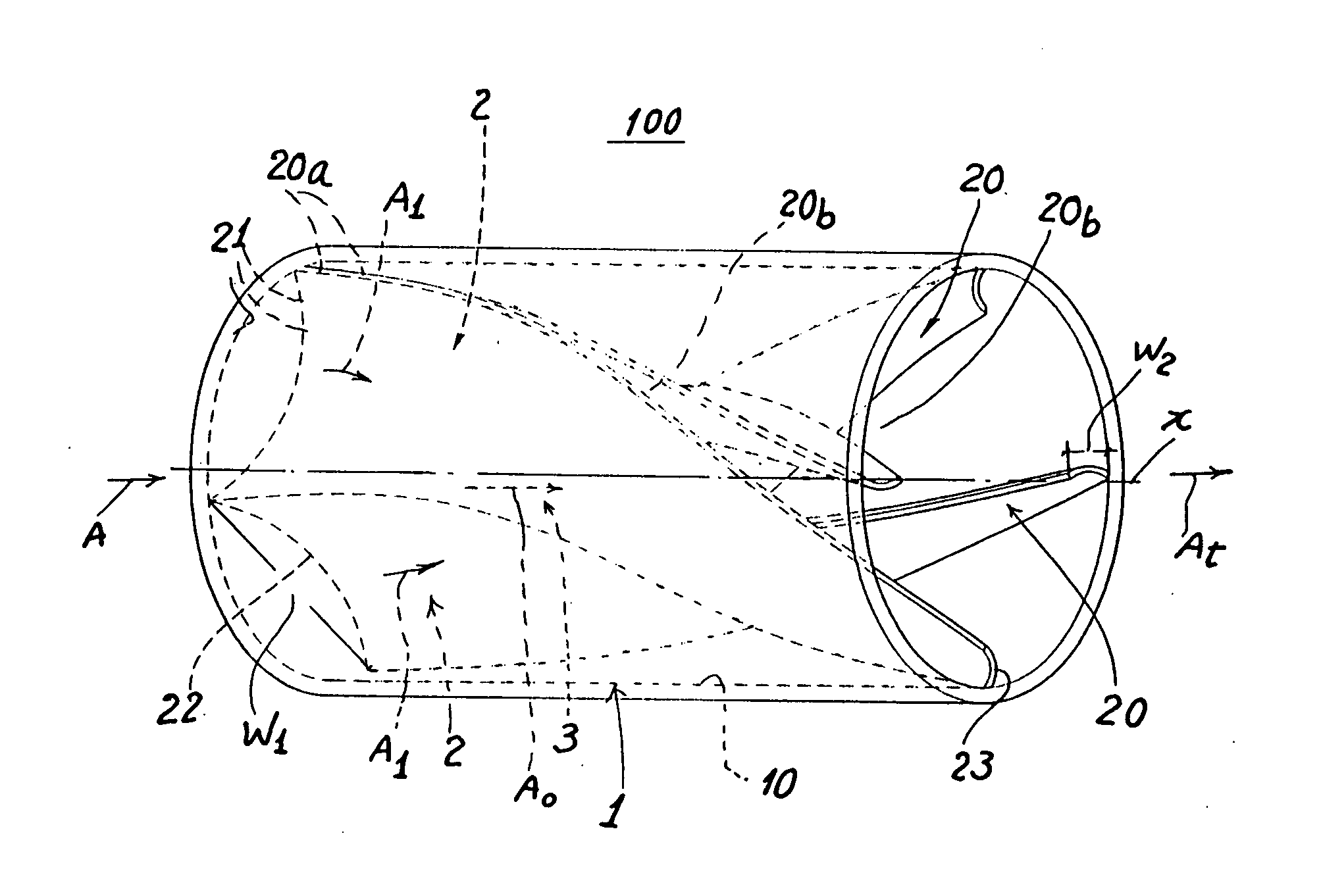
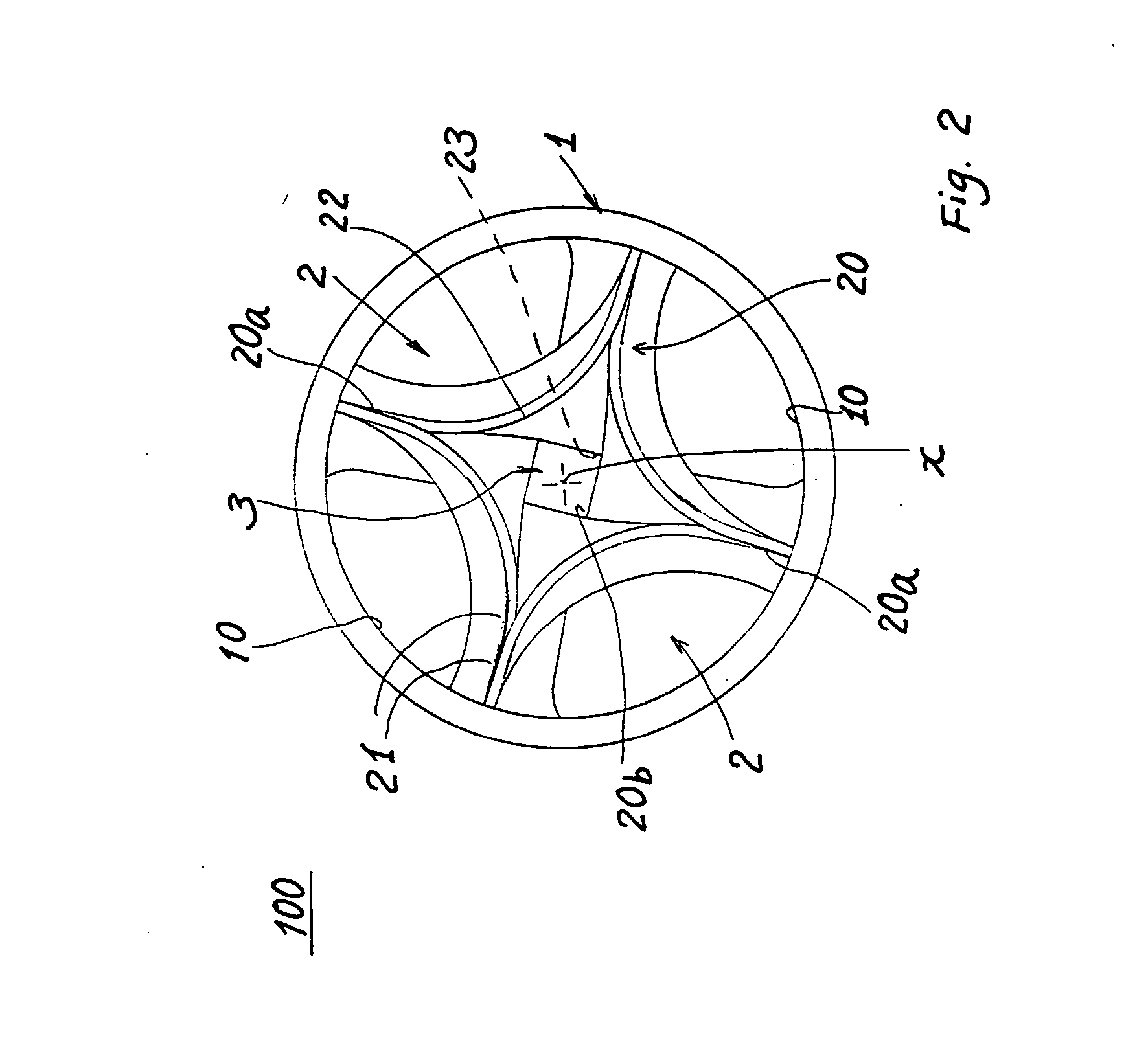
[0014] As shown in FIGS. 1-4, the present invention comprises an air swirling device 100 inserted or connected in an air inlet pipe or hose 6 as connected in between an air cleaner 4 and an internal combustion engine 5 of a car or the like as shown in FIG. 4.
[0015] The air swirling device 100 of the present invention comprises: a pipe member 1 connected in between an air cleaner 4 and an engine 5 (as shown in FIG. 4) or inserted in an air inlet pipe 6 between the air cleaner 4 and the engine 5; a plurality of swirl-flow ducts 2 spirally formed in the pipe member 1 about an axis X defined at a longitudinal center of the pipe member 1; and a central-flow duct 3 axially formed in the pipe member 1 and surrounded by the plurality of swirl-flow ducts 2; whereby upon suction by the engine, the inlet air flow A will be swirled as guided by the plurality of swirl-flow ducts 2 to form a plurality of streams of swirling air flow A1 to be combined with a central air flow A0 through the centra...
PUM
 Abstract
Description
Claims
Application Information
 - Generate Ideas
- Intellectual Property
- Life Sciences
- Materials
- Tech Scout
- Unparalleled Data Quality
- Higher Quality Content
- 60% Fewer Hallucinations
Browse by: Latest US Patents, China's latest patents, Technical Efficacy Thesaurus, Application Domain, Technology Topic, Popular Technical Reports.
© 2025 PatSnap. All rights reserved.Legal|Privacy policy|Modern Slavery Act Transparency Statement|Sitemap|About US| Contact US: help@patsnap.com