
Mechanism for the draft of a high frequency atomization device

a high-frequency atomization and atomization device technology, which is applied in the direction of medical devices, liquid spraying apparatus, other medical devices, etc., can solve the problems of large portion of kinetic energy assimilated by liquid and wasted, non-uniform amount of atomization and excitation, and insufficient amount of medicinal value of excited mis

Inactive Publication Date: 2007-07-26
KAI CHIH IND
View PDF9 Cites 20 Cited by
  • Summary
  • Abstract
  • Description
  • Claims
  • Application Information

AI Technical Summary

Benefits of technology

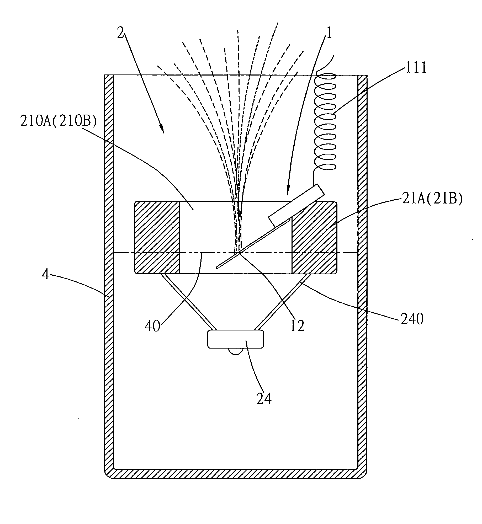
[0012] In light of the aforementioned shortcomings, the present invention uses a piezoelectric ceramic actuator that is cantilever connected to a vibratable plate to expose the vibratable plate. A free end of the vibratable plate is submerged beneath a liquid surface at an operating position, and the entire structure floats on the liquid surface of an operating liquid using a floating support. The vibrational waves that are produced directly act on the liquid surface, and a portion of the energy is transmitted to the liquid to produce a mixing effect. The vibratable plate maintains a definite directed amount of effect on the liquid surface, and is able to acquire comparable load conditions and bring into effect quantitative power.

Problems solved by technology

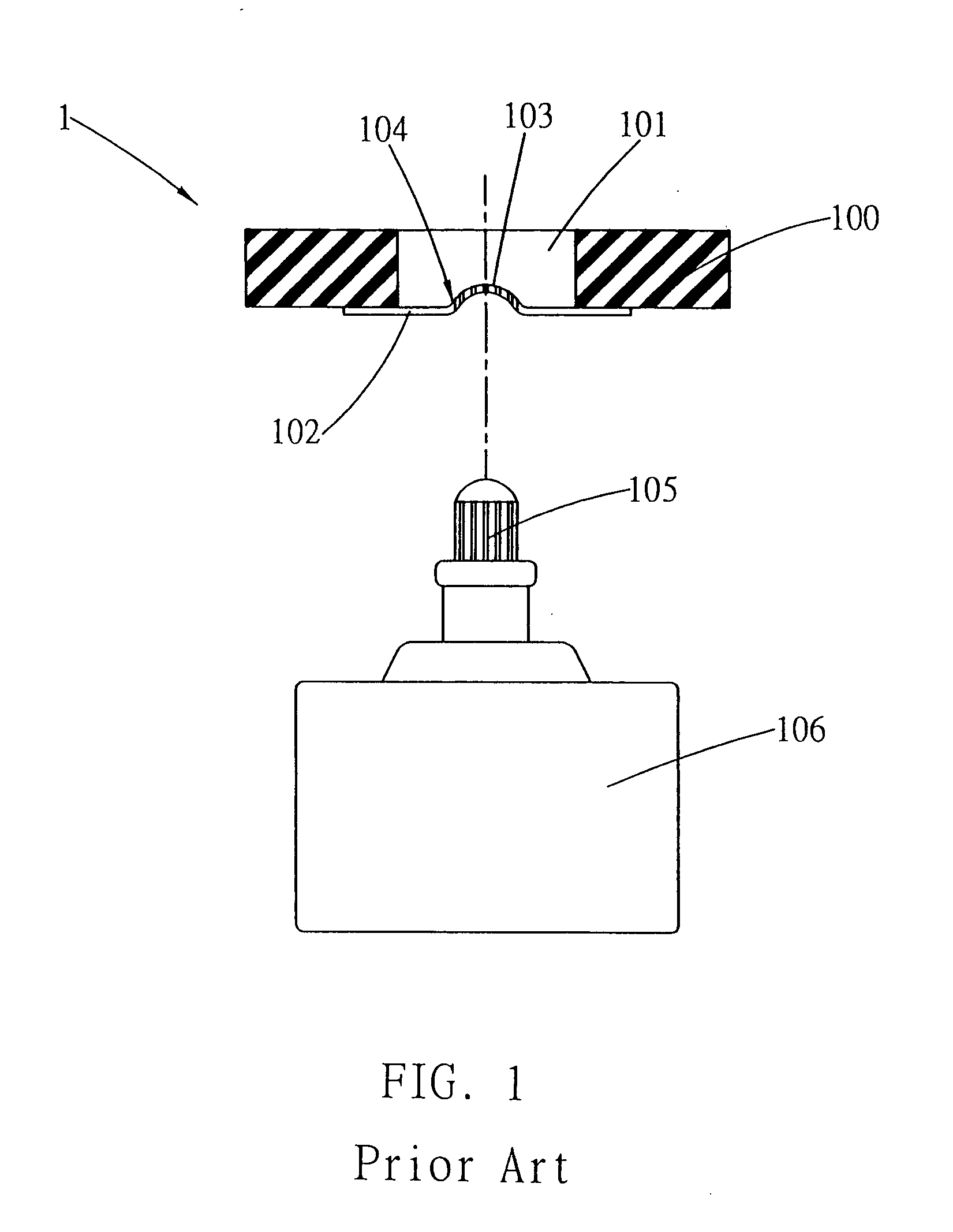
Because each of the aforementioned vibrating actuators is positioned within the liquid, thus, the largest portion of the kinetic energy is assimilated by the liquid and wasted.
Hence, design of the liquid guide fiber 105 affects efficiency of its capillarity effect, and results in a nonuniform amount of atomization and excitation formed.
Furthermore, the capillarity phenomenon of the liquid guide fiber 105 produces a filter effect that further results in the excited mist carrying an insufficient amount of medicinal value.
Poor affinity between the medicinal substances and the liquid filled in the container 106 results in a static state within the container 106 that results in the inability to produce a mixing effect between the medicinal substances and the liquid solution, thereby causing the liquid drawn up by the liquid guide fiber 105 to be separated from the medicinal substances.

Method used


Image

  • Mechanism for the draft of a high frequency atomization device
  • Mechanism for the draft of a high frequency atomization device
  • Mechanism for the draft of a high frequency atomization device

Examples


Embodiment Construction

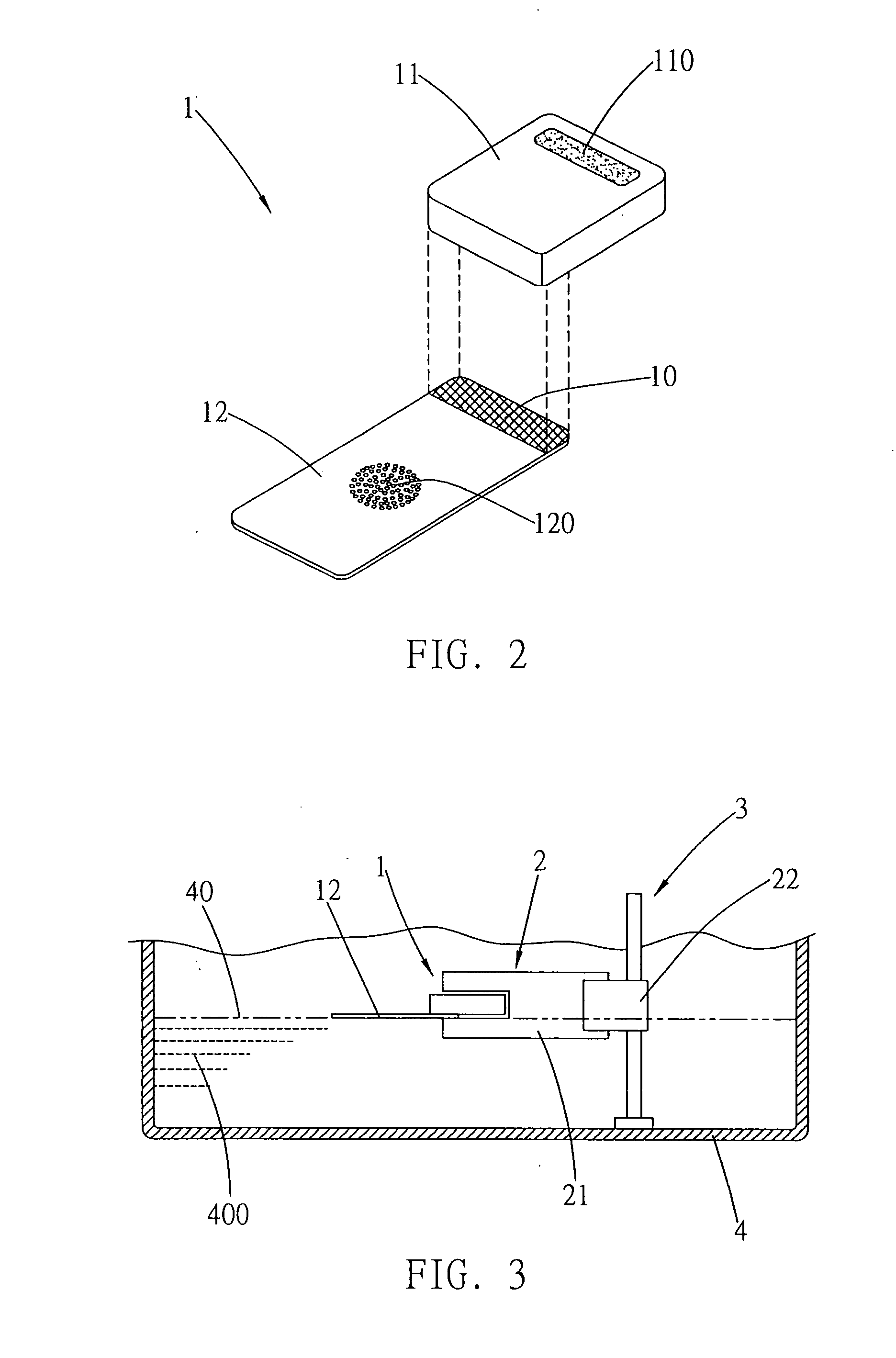
[0038] Referring to FIG. 2, which shows an embodiment of an excitation device 1 of the present invention, primarily structured to comprise a vibratable plate 12 joined to a side of a block piezoelectric ceramic actuator 11 using a cantilever method. A joining surface 10 formed on one side of the vibratable plate 11 is used to join to a corresponding end of an underside of the actuator 11. The joining surface 10 can be joined to the actuator 11 using any mechanical or hardware component or agglutination or soldering method.

[0039] Vibratable holes 120 are defined in a breadth of the vibratable plate 12. The vibratable holes 120 are minute circular holes that are densely assembled to form a distributed geometric area. Height position of the vibratable holes 120 is such to be adjacent to a surface of a liquid.

[0040] An exterior surface of the actuator 11 is coated with a dielectric coating 110 that enables electrical connection to be established with a power cable.

[0041] Referring to...


PUM


Abstract

A mechanism for the draft of a high frequency atomization device, which has particular application to supporting a cantilever excitation device on the surface of a large amount of operating liquid using a floating support method, thereby enabling a vibratable plate to accurately position on the liquid surface of any height and bring into effect quantitative power. The excitation device is structured from a block piezoelectric ceramic actuator and the vibratable plate, which extends from one side of the actuator and joined thereto using a cantilever method. The excitation device floats on the liquid surface of the operating liquid using a floating support. An operating side of a free end of the vibratable plate maintains a definite directed amount of effect on the liquid surface, and is able to acquire comparable load conditions and bring into effect quantitative power.

Description

BACKGROUND OF THE INVENTION [0001] (a) Field of the Invention [0002] The present invention relates to a mechanism for the draft of a high frequency atomization device, which has particular application to supporting an excitation device on the surface of a large amount of operating liquid using a floating support method. After supporting the excitation device, the vibratable plate is able to acquire comparable load conditions and bring into effect quantitative power. [0003] (b) Description of the Prior Art [0004] A conventional liquid atomization device primarily uses high frequency vibrating equipment immersed in an aqueous liquid to excite vibrating energy waves that break up the liquid surface to from a mist, or a vibrating equipment, interior of which is joined to and actuates a vibratable plate, is used to cause wave motion kinetic energy excitation of the aqueous liquid. [0005] If a disk-type piezoelectric ceramic is positioned beneath the liquid surface, after supplying electr...

Claims


Application Information

Patent Timeline
Patent Type & Authority Applications(United States)
IPC IPC(8): A61M11/00B05B17/06
CPCA61M11/005B05B17/0638B05B17/0615A61M2202/064
Inventor CHEN, WEN-PINJEAN, NAI-YING
Owner KAI CHIH IND
Learn More