Starter

a technology of starter and yoke, which is applied in the direction of starter, machine/engine, transportation and packaging, etc., can solve the problems of insufficient tightening and water proofing capability of starter and motor terminal, and conventional techniques cannot provide adequate tightening. to achieve the effect of reducing the number of manufacturing steps

Inactive Publication Date: 2007-07-26
DENSO CORP
View PDF4 Cites 3 Cited by
  • Summary
  • Abstract
  • Description
  • Claims
  • Application Information

AI Technical Summary

Benefits of technology

[0016]Because the connector bar and the motor terminal are made of a rigid body and the field coil is made of a plane shaped conductor (, not made of stranded or twisted wire), both of the connector bar and the motor terminal are positioned when the connector bar is fixed to the end part of the field coil. Accordingly, it is possible to assemble the gromm

Problems solved by technology

As a result, because the grommet is compressed only toward the end frame side from the motor terminal side, but do not compressed toward the yoke side from the motor terminal, such a conventional configuration of the starter cannot obtain a necessary wat

Method used


Image

  • Starter
  • Starter
  • Starter

Examples


embodiment

[0025]A description will be given of a configuration, functions and effects of a starter 1 according to an embodiment of the present invention with reference to FIG. 1 to FIG. 6.

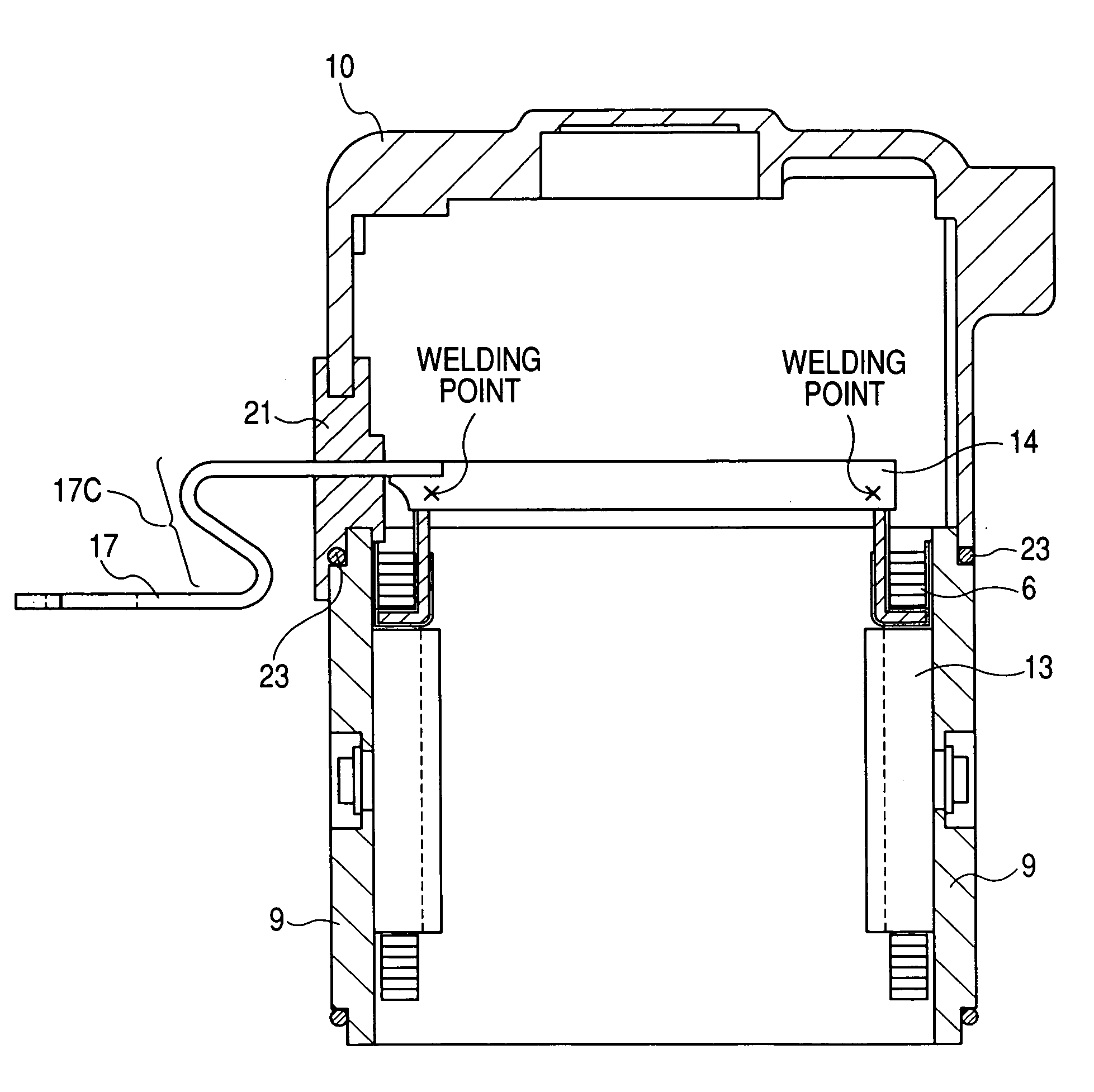
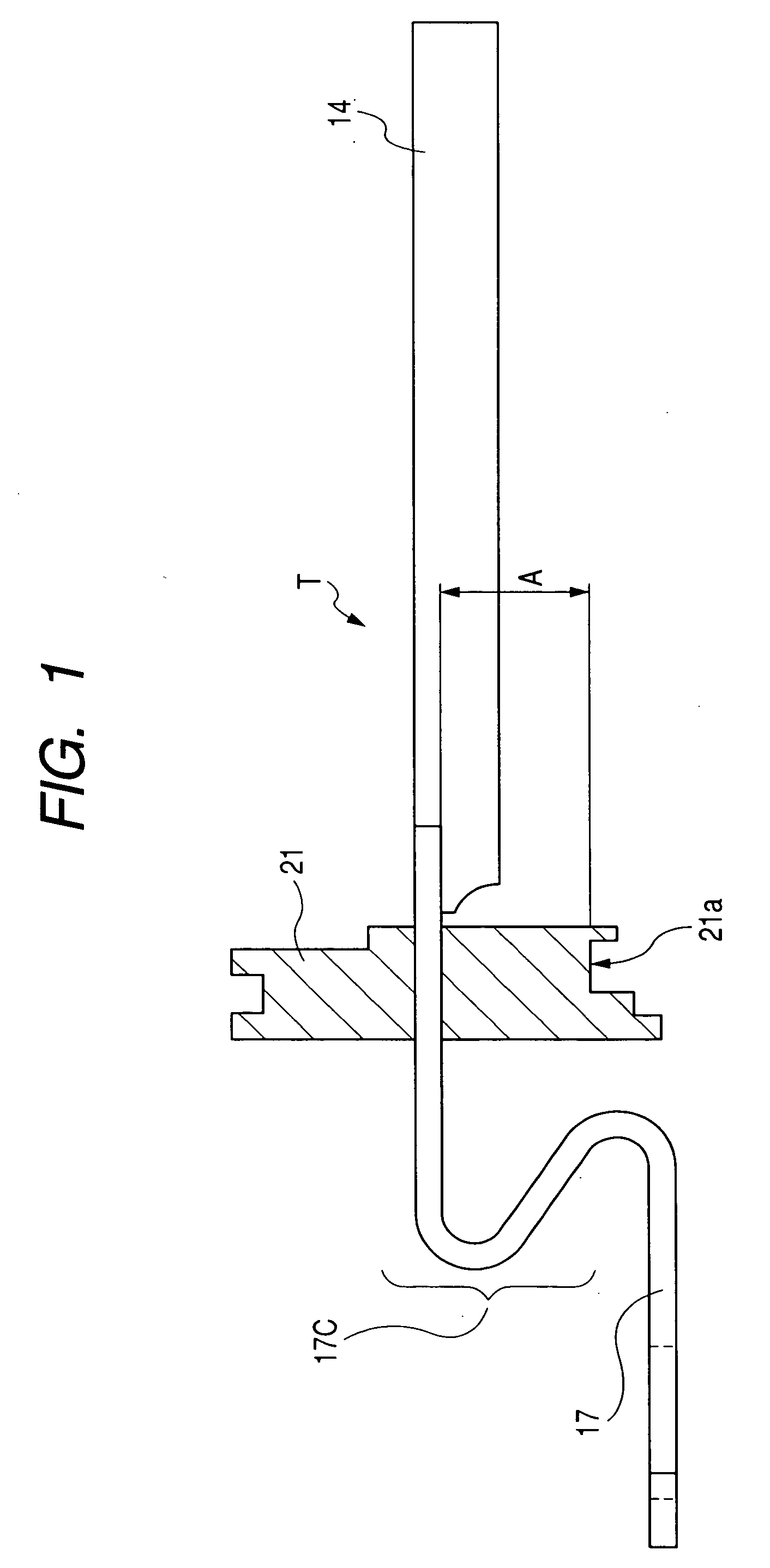
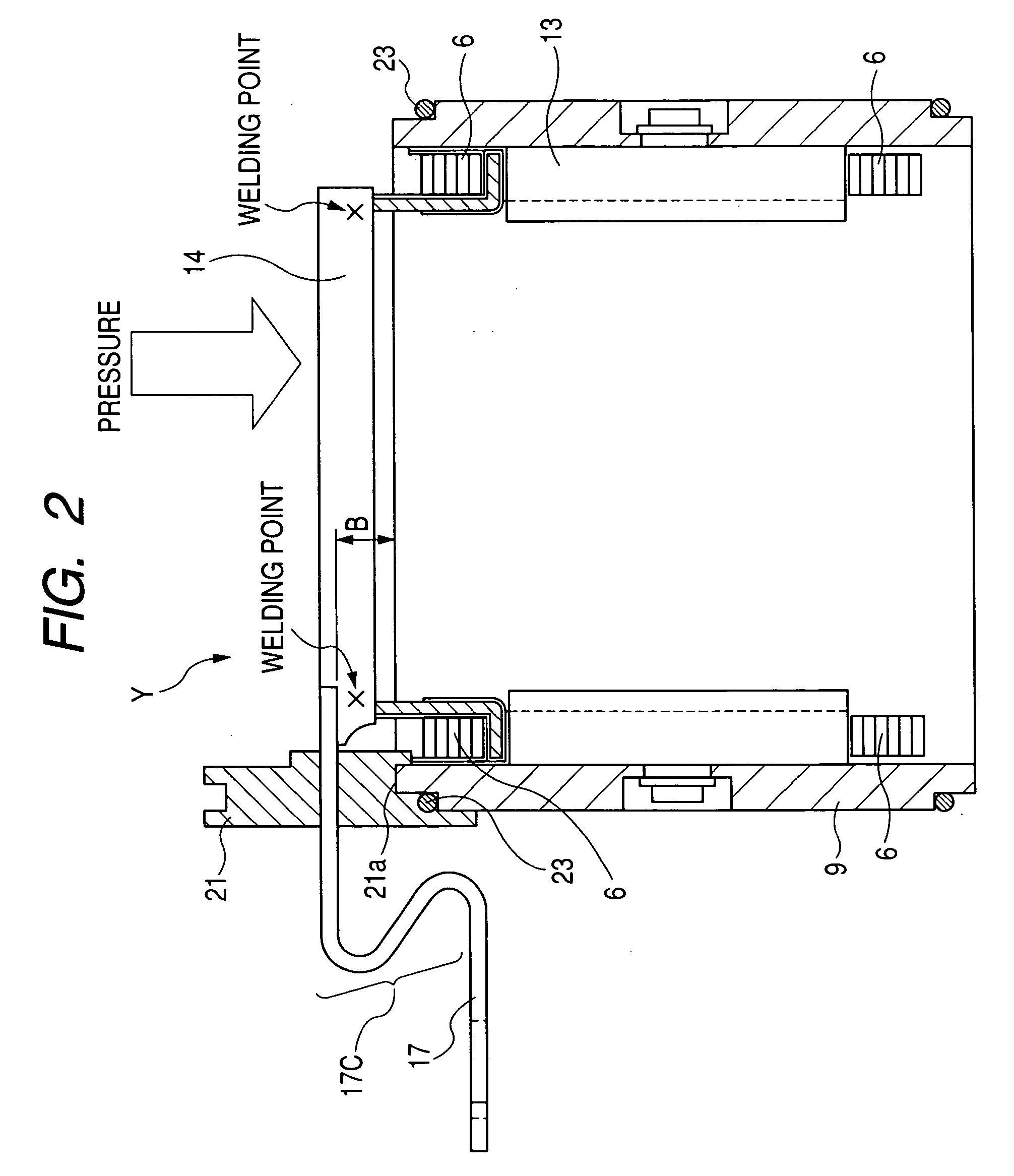
[0026]FIG. 1 is a side view of a terminal assembly (ass'y), designated by reference character “T”, in the starter 1 of the embodiment. FIG. 2 is a sectional view of a yoke assembly, designated by reference character “Y”, incorporated in the starter 1 of the embodiment. FIG. 5 is a sectional view showing a part of the starter 1 of the embodiment of the present invention.

[0027]As shown in FIG. 5, the starter 1 is composed mainly of an electric motor 2, a magnet switch 3, an output shaft 4, and a pinion 5. The starter 1 cranks an internal combustion engine (omitted from the drawings). The electric motor 2 generates the revolution power. The magnetic switch 3 opens and closes (namely, performs ON / OFF of) a main contact (which will be explained later) of an electric circuit for the electric motor 2. The output sh...

modified example

[0046]The embodiment of the present invention described above has disclosed the positioning of both the connector bar 14 and the motor terminal 17 by welding the connector bar 14 to the end terminal of the field coil 6. The concept of the present invention is not limited by this. For example, it is acceptable to use an insulator 24 capable of electrically insulating the connector bar 14 from the yoke 9. FIG. 6 shows the insulator 24 incorporated in the yoke assembly Y that is covered with the end frame 10. That is, both of the connector bar 14 and the motor terminal 17 are positioned by the power of the insulator to support the connector bar 14 while satisfying the relationship (1) described above. Because this manner does not require the positioning of the connector bar 14 by welding the connector bar 14 and the field coil 16, it is possible to use a stranded wire or twisted wire as a bundle made of plural fine insulated wires.


PUM

PropertyMeasurementUnit
Resilienceaaaaaaaaaa

Abstract

In a starter, a motor terminal is composed of a rigid body made of metal, supported by a grommet, and welded to a connection bar in order to construct a terminal assemble (ass'y). The terminal assemble is constructed into a yoke assemble under the grommet is attached to an opening part of the yoke and the connection bar is welded to an end part of a field coil. An interval between a sealing surface of the grommet and the motor terminal in the yoke assembly, namely before constructing the yoke assembly is smaller than an interval between in the terminal assembly, namely, before constructing the yoke assembly. The grommet has thereby a water proof capability because the grommet is pressed not only the end frame side but also toward the yoke side through the motor terminal when the grommet between the yoke assembly and the end frame is fastened or compressed by through-bolts.

Description

CROSS-REFERENCE TO RELATED APPLICATIONS[0001]This application is related to and claims priority from Japanese Patent Application No. 2006-17872 filed on Jan. 26, 2006, the contents of which are hereby incorporated by reference.BACKGROUND OF THE INVENTION[0002]1. Field of the Invention[0003]The present invention relates to a starter equipped with a motor terminal having a rigid body made of metal supported by a grommet.[0004]2. Description of the Related Art[0005]Japanese patent laid open publication No. JP 2005-120873 has disclosed a conventional starter equipped with a motor terminal having a rigid body which is made of steel, for example. The motor terminal is supported by a grommet made of rubber fastened and supported between a yoke and an end frame. One terminal of the motor terminal, which is extending to the outside of the yoke, is electrically connected to a terminal of a magnetic switch. The other terminal of the motor terminal is extending to the inside of the yoke and fix...

Claims


Application Information

Patent Timeline
IPC IPC(8): H02K11/00
CPCB23K2201/006F02N11/00F02N15/00Y10T29/49009H01R39/32H02K5/225H02K15/0062H01R4/029B23K2101/006
Inventor INOUE, HISATOHASEGAWA, YOUICHIMURASE, KAZUAKI
Owner DENSO CORP
Why Eureka
Try Eureka